Method and device for detaching a component which is attached to a flexible film

A film and component technology, which is applied in the field of separating and device parts for bonding on a flexible film, can solve problems such as the position problem of the edge area of ​​the wafer

Active Publication Date: 2010-06-16
库力科及索法模压焊接有限责任公司
View PDF10 Cites 0 Cited by
  • Summary
  • Abstract
  • Description
  • Claims
  • Application Information

AI Technical Summary

Problems solved by technology

Furthermore, depending on the size of the chip, corresponding space is required laterally for movement, which can lead to positional problems in the edge region of the wafer

Method used


Image

  • Method and device for detaching a component which is attached to a flexible film
  • Method and device for detaching a component which is attached to a flexible film
  • Method and device for detaching a component which is attached to a flexible film

Examples


Embodiment Construction

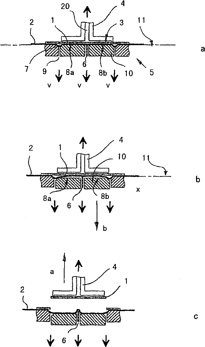
[0038] exist figure 1 A first embodiment of the split process with three steps is shown in a to 1c. Here, a plurality of chips 1 are glued onto a stretched wafer film 2, or the wafer that was bonded together is divided into individual chips by sawing. After sawing, the film is further tensioned in a known manner in order to facilitate the separation of the chips. The separate tool, indicated as a whole by 5, is only shown schematically here. It is arranged stationary in the working machine relative to the wafer film 2 . The placement of the chips 1 on the parting tool 5 takes place by means of an X-Y coordinate drive.

[0039] A holding tool 4 with a flat, suction-action holding surface can rest against the surface 3 of the chip facing away from the film. A negative pressure is applied to this surface via the negative pressure channel 20 , so that the chip adheres to the holding tool 4 . Holding tool 4 can be raised along arrow direction a under the situation of maintaini...


PUM


Abstract

The invention relates to a film (2) which comprises a component (1) to be detached therefrom. Said film is placed in the area of the component on a detaching tool (5) that is provided with at least one supporting element (6) for the film, which extends in a plane of support (11). The film is sucked against the support element (6) and partially under the plane of support by exerting negative pressure. The area of the supporting element is provided with at least one surface section (8) which extends in the plane of support when the detaching process begins, and which can be displaced, once the component (1) is grasped by a suction tool (4), plane-parallel to the plane of support while the negative pressure is maintained. The invention allows to control the detaching process of the film in acontrolled movement without damaging or displacing the component.

Description

technical field [0001] The invention relates to a method for separating components bonded to flexible films. This method is used especially in the processing of semiconductor chips to remove a plurality of chips from a wafer film in quick succession and place them on a base. The invention also relates to a device for separating parts bonded to a flexible film. Background technique [0002] The semiconductor chips on which the electronic circuits are arranged are hereby previously separated by sawing from silicon disks known as wafers. The wafer is bonded at the latest for the sawing process to a wafer film which is tensioned on a frame, wherein the attachment must be clearly high enough to avoid cracks or separation of the chips during the sawing process, on the contrary, from This attachment should be as small as possible when separating the individual chips on the film, in order to avoid exerting excessive mechanical forces on the chips. [0003] Methods and devices are...

Claims


Application Information

Patent Timeline
Patent Type & Authority Patents(China)
IPC IPC(8): H01L21/00
CPCH01L21/67132Y10S438/976Y10T156/1132Y10T156/1944H01L21/02
Inventor 乔基姆·特林克斯安德烈亚斯·马特沃尔夫冈·赫布斯特
Owner 库力科及索法模压焊接有限责任公司
Why Eureka
Try Eureka