Beating machine for paper production

A beating machine and beating barrel technology, applied in the field of papermaking equipment, can solve the problems of low crushing degree, inconsistent density, inconvenient production, etc., and achieve the effects of improving stability, consistent crushing density, and improving crushing effect

Pending Publication Date: 2018-07-06
郑州华美彩印纸品有限公司
View PDF6 Cites 2 Cited by
  • Summary
  • Abstract
  • Description
  • Claims
  • Application Information

AI Technical Summary

Problems solved by technology

[0004] The purpose of the present invention is to solve the problem that in the prior art, the degree of crushing at the position close to the wall of the crushing barrel in the papermaking beating machine is not high, which leads to inconsistent density of the pulp crushed in the beating machine, which brings great inconvenience to production and is extremely difficult. Greatly affects the efficiency and quality of production, thereby providing a beater for paper production, which has the effect of targeted crushing of the slurry on the wall of the crushing barrel, and has the effect of consistent crushing density of the pulp in the entire crushing barrel

Method used


Image

  • Beating machine for paper production
  • Beating machine for paper production
  • Beating machine for paper production

Examples


Embodiment 1

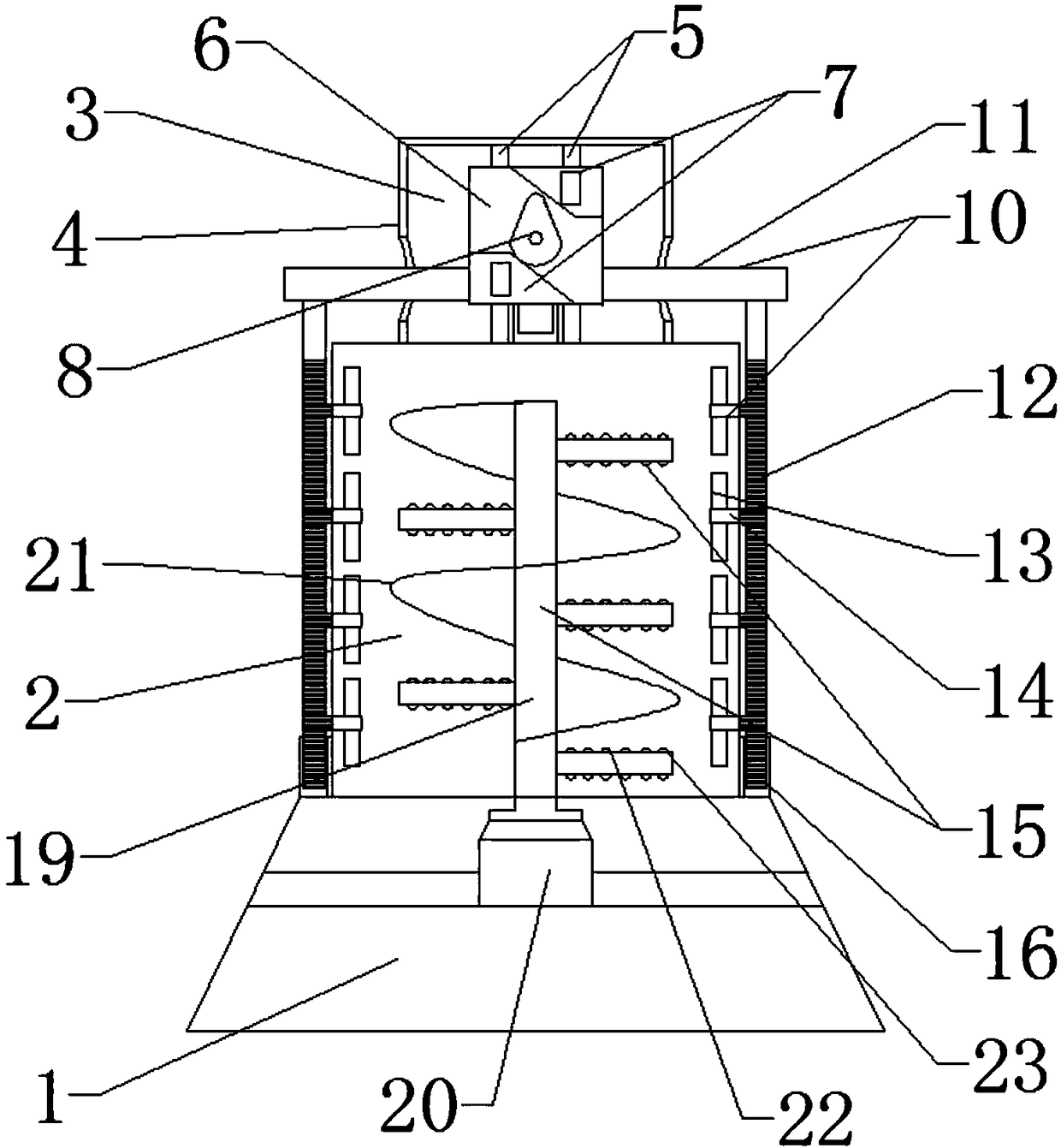
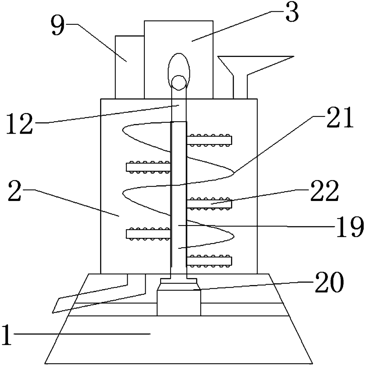
[0031]A beating machine for papermaking, comprising a base 1, a beating bucket 2 arranged on the upper end of the base 1, the upper end of the beating bucket 2 is provided with a lifting device 3, the lifting device 3 includes a lifting shell 4, the lifting shell 4 is provided with a chute 5 and a slider 6 moving along the length direction of the chute 5. A pair of power transmission blocks 7 are arranged on one side of the slider 6, and a cam 8 is arranged between the power transmission blocks 7. The main shaft of the cam 8 is connected with a motor 9, and the motor 9 is placed on one side of the lifting shell 4; the other two sides of the slider 6 are connected with a bucket wall beating assembly 10; Connected moving rod 11, the moving rod 11 passes through the lifting shell 4, the other end of the moving rod 11 is connected with a rack 12, the rack 12 is placed on the outside of the beating barrel 2, the rack 12, the central axis is parallel to the central axis of the beati...

Embodiment 2

[0033] On the basis of Embodiment 1, the lower end of the rack 12 is provided with a sliding sleeve 16, the sliding sleeve 16 is sleeved on the lower end of the rack 12, and the other end of the sliding sleeve 16 is fixed on the base 1 , the lower end of the rack 12 slides up and down along the path of the sliding sleeve 16 length.

Embodiment 3

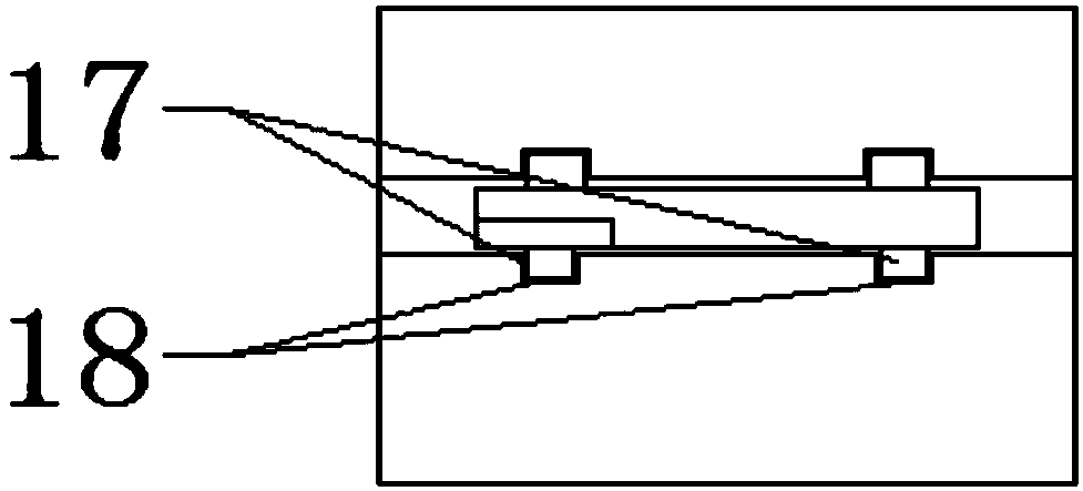
[0035] On the basis of Embodiment 2, the other end surface of the power transmission block 7 is provided with a slider B17, and the side of the lifting housing 4 adjacent to the slider B17 is provided with a chute matching the slider B17 B18.


PUM


Abstract

The invention discloses a beating machine for paper production, belongs to the field of paper production equipment, and aims at providing the beating machine with a uniform pulverizing effect. The machine is characterized in that a sliding groove is formed in a lifting housing, a sliding block which moves in the length direction of the sliding groove is arranged in the lifting housing, a cam is arranged between power transmission blocks, the main shaft of the cam is connected with a motor, and two other side faces of the sliding block are connected with bucket wall beating assemblies; the bucket wall beating assemblies comprise moving rods which are slidably connected with the sliding block, the other ends of the moving blocks are connected with racks, the racks are arranged on the outer side of a beating bucket, a plurality of beating blades are arranged on the inner wall of the beating bucket, the main shafts of the beating blades penetrate through the beating bucket, and the other ends of the main shafts of the beating blades mesh with the racks. The invention provides a beating machine with a targeted pulverizing effect on pulp on the wall of a pulverizing bucket and capable ofachieving uniform pulverizing density of the pulp in the whole pulverizing bucket.

Description

technical field [0001] The invention belongs to the field of papermaking equipment, and in particular relates to a beating machine used for papermaking. Background technique [0002] Paper is the most commonly used item in our daily life. Whether we are reading, reading newspapers, writing or drawing, we have to come into contact with paper. In the production of industry, agriculture and defense industry, paper is also inseparable. Papermaking is an important invention of the working people in ancient China. There are two forms of mechanism and manual. The mechanism is carried out continuously on the paper machine. The pulp suitable for the paper quality is diluted with water to a certain concentration, and is initially dehydrated in the wire part of the paper machine to form a wet paper sheet, which is dehydrated by pressing and then dried into paper. Papermaking is An important invention of the working people of the Han nationality in ancient times. There are two forms...

Claims


Application Information

Patent Timeline
Patent Type & Authority Applications(China)
IPC IPC(8): D21D1/02
CPCD21D1/02
Inventor 马艳超
Owner 郑州华美彩印纸品有限公司
Why Eureka
Try Eureka