Linear friction welding process between aluminium part and steel part

A technology of linear friction welding and steel parts, applied in welding equipment, manufacturing tools, non-electric welding equipment, etc., which can solve the problems of reduced mechanical properties of connectors, inability to use welded joints, and low production efficiency.

Inactive Publication Date: 2007-08-22
NORTHWESTERN POLYTECHNICAL UNIV
View PDF0 Cites 36 Cited by
  • Summary
  • Abstract
  • Description
  • Claims
  • Application Information

AI Technical Summary

Problems solved by technology

However, the disadvantages of this welding method are: 1. It is only suitable for pure aluminum or rust-proof aluminum with good plasticity; 2. It can only be used for welding thin aluminum plates to the surface of steel plates, but not for other welding joint forms
This mechanical aluminum-steel member connection method also has the following disadvantages: 1. The structure of the connection part is complicated, so the cost of the parts is high and the production efficiency is low; 2. The gap at the joint of the aluminum-steel connector not only affects the use effect of the member, And the fretting fatigue caused by the assembly gap will reduce the mechanical properties of the connecting parts, especially the poor fatigue strength, so the safety factor of the components is low

Method used


Image

  • Linear friction welding process between aluminium part and steel part

Examples


Embodiment 1

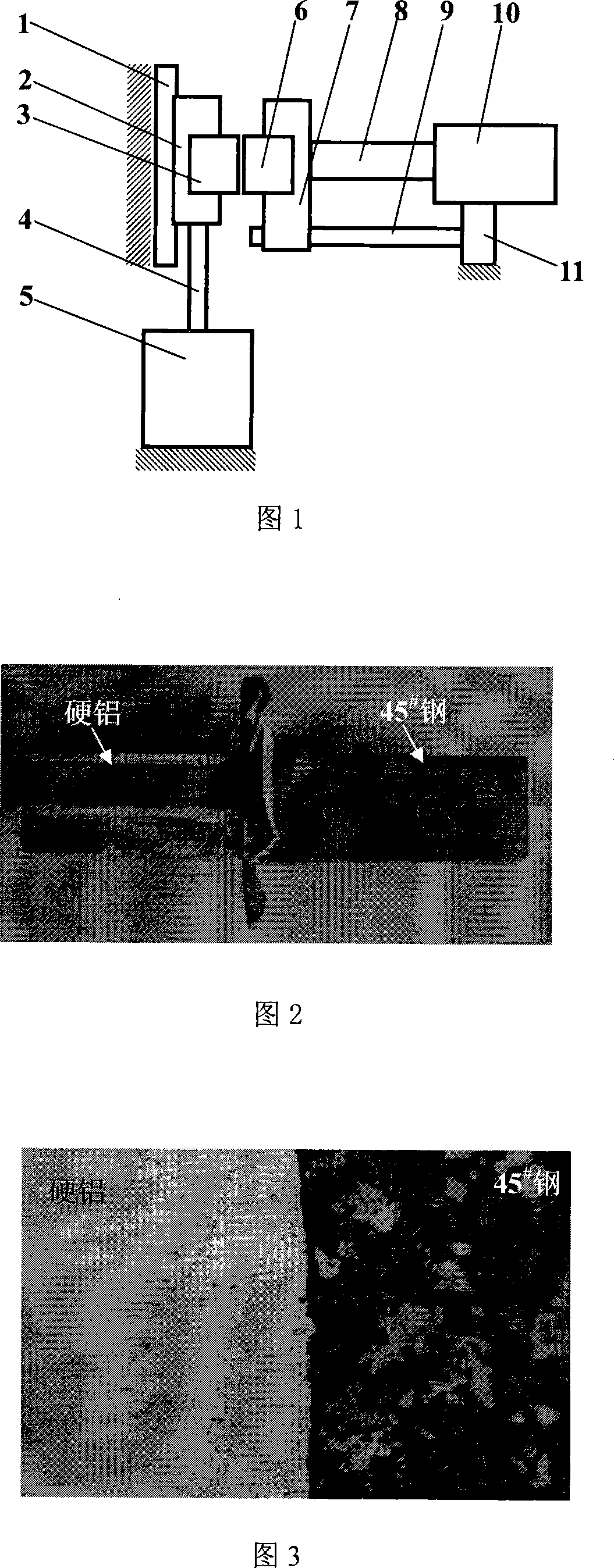
[0015] Embodiment 1: Referring to FIG. 1 , the welding of an aluminum part with a rectangular cross section and a steel part. Install and fix the steel part 3 in the vibrating fixture 2. The vibration source 5 drives the vibration fixture 2 to reciprocate up and down along the linear guide rail 1 with a vibration frequency of 24 Hz and an amplitude of 2 mm through the connecting rod 4 . The steel part 3 vibrates up and down with the vibrating fixture 2 at the same frequency. The aluminum parts 6 are installed and fixed in the mobile fixture 7 . The afterburner cylinder 10 makes the movable fixture 7 move left and right along the slide bar 9 through the thrust rod 8, and the aluminum part 6 is promptly subjected to left or right thrust at the same time.

[0016] During welding, under the promotion of the booster cylinder 10, the steel part 3 and the aluminum part 6 are in contact with each other. At this time, the vibration source 5 drives the steel part 3 to vibrate rapidly...

Embodiment 2

[0019] Embodiment 2: Referring to FIG. 1 , the welding of an aluminum part with a circular cross section and a steel part. Install and fix the steel part 3 in the vibrating fixture 2. The vibration source 5 drives the vibration fixture 2 to reciprocate up and down along the linear guide rail 1 with a vibration frequency of 26 Hz and an amplitude of 2.6 mm through the connecting rod 4 . The steel part 3 vibrates up and down with the vibrating fixture 2 at the same frequency. The aluminum parts 6 are installed and fixed in the mobile fixture 7 . The afterburner cylinder 10 makes the movable fixture 7 move left and right along the slide bar 9 through the thrust rod 8, and the aluminum part 6 is promptly subjected to left or right thrust at the same time.

[0020] During welding, under the promotion of the booster cylinder 10, the steel part 3 and the aluminum part 6 are in contact with each other. At this time, the vibration source 5 drives the steel part 3 to vibrate rapidly ...

Embodiment 3

[0021] Embodiment 3: Referring to FIG. 1 , the welding of an aluminum part with a regular hexagonal cross section and a steel part. Install and fix the steel part 3 in the vibrating fixture 2. The vibration source 5 drives the vibration fixture 2 to reciprocate up and down along the linear guide rail 1 with a vibration frequency of 28 Hz and an amplitude of 2.6 mm through the connecting rod 4 . The steel part 3 vibrates up and down with the vibrating fixture 2 at the same frequency. The aluminum parts 6 are installed and fixed in the mobile fixture 7 . The afterburner cylinder 10 makes the movable fixture 7 move left and right along the slide bar 9 through the thrust rod 8, and the aluminum part 6 is promptly subjected to left or right thrust at the same time.

[0022] During welding, under the promotion of the booster cylinder 10, the steel part 3 and the aluminum part 6 are in contact with each other. At this time, the vibration source 5 drives the steel part 3 to vibrate...


PUM


Abstract

The linear friction welding process between aluminum part and steel part includes the following steps: fixing the steel part in a vibrating fixture; vibrating the steel part vertically by means of a vibrating source and a link rod and at 24-30 Hz frequency and 2.0-2.8 mm amplitude; fixing the aluminum part in a movable fixture; contacting the steel part and the aluminum part mutually with a pushing oil cylinder in the friction pressure of 3.5-5.5 Kg / sq mm for 1.5-2.0 sec; stopping vibration and applying forging pressure of 6.5-12.0 Kg / sq mm for 0.5-1 sec; and cooling naturally to form firm joint between the aluminum part and the steel part. The present invention controls the temperature in friction area at 0.8 time the smelting point of aluminum and applying forging pressure to produce plastic deformation so as to weld by means of re-crystallization and the atomic combination between aluminum and steel.

Description

technical field [0001] The invention relates to a welding method of aluminum parts and steel parts, in particular to a linear friction welding method of aluminum parts and steel parts. Background technique [0002] Aluminum itself is a metal material with poor weldability, especially duralumin and super duralumin have a strong tendency of thermal cracking, and its weldability is even worse. However, the thermophysical properties of aluminum and steel are very different, and it is extremely difficult to realize the welding of these two materials, which has always been a technical problem in the field of continuous exploration and research in the field of welding. [0003] There are two known methods for welding aluminum parts and steel parts together and for actual production: one is explosive welding; the other is rotary friction welding. [0004] Explosive welding is a method that can weld pure aluminum or rust-proof aluminum with better plasticity to large-area steel plat...

Claims


Application Information

Patent Timeline
Patent Type & Authority Applications(China)
IPC IPC(8): B23K20/12B23K103/20
Inventor 马铁军杨思乾张勇席德科
Owner NORTHWESTERN POLYTECHNICAL UNIV
Why Eureka
Try Eureka