
Side leaking photon crystal optical fiber and producing method thereof

A technology of photonic crystal fiber and leaky type, which is applied in the direction of cladding fiber, optical waveguide light guide, glass manufacturing equipment, etc., can solve the problems of long scrambled mode length of single-polarization single-mode photonic crystal fiber, strict process requirements, and difficult production

Inactive Publication Date: 2007-08-22
BEIJING JIAOTONG UNIV
View PDF0 Cites 5 Cited by
  • Summary
  • Abstract
  • Description
  • Claims
  • Application Information

AI Technical Summary

Problems solved by technology

Just because the photonic crystal fiber has a strong ability to confine light waves, the scrambling length of the single-polarization single-mode photonic crystal fiber is long, the rotation detection sensitivity is not high, and the process requirements of the single-polarization single-mode photonic crystal fiber are very strict on the fiber microstructure. , difficult to manufacture, high cost

Method used


Image

  • Side leaking photon crystal optical fiber and producing method thereof
  • Side leaking photon crystal optical fiber and producing method thereof
  • Side leaking photon crystal optical fiber and producing method thereof

Examples


Embodiment 1

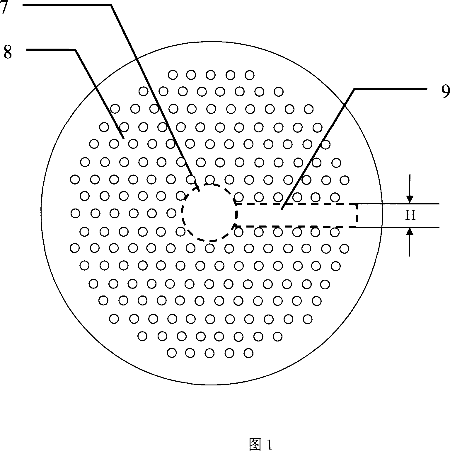
[0021] Embodiment 1: a high equivalent refractive index linear area side leakage type triangular lattice quartz photonic crystal fiber, the cross-sectional structure is shown in Figure 1, it includes a pure silica high refractive index core region 7 that transmits light waves and surrounds the core region 7 and The cladding region 8 that constrains the transmission of light waves, the cladding region 8 is a low equivalent refractive index region formed by capillary pores parallel to the axial direction and arranged in a triangular lattice. The structural feature of the present invention is: there is a The region 7 is parallel to the pure quartz high equivalent refractive index linear region 9 extending outward from the core region 7 through the cladding region 8, and the cross-sectional height H of the pure quartz high equivalent refractive index linear region 9 is half the wavelength of the transmitted light value.

[0022] A side-leakage triangular lattice quartz photonic cr...

Embodiment 2

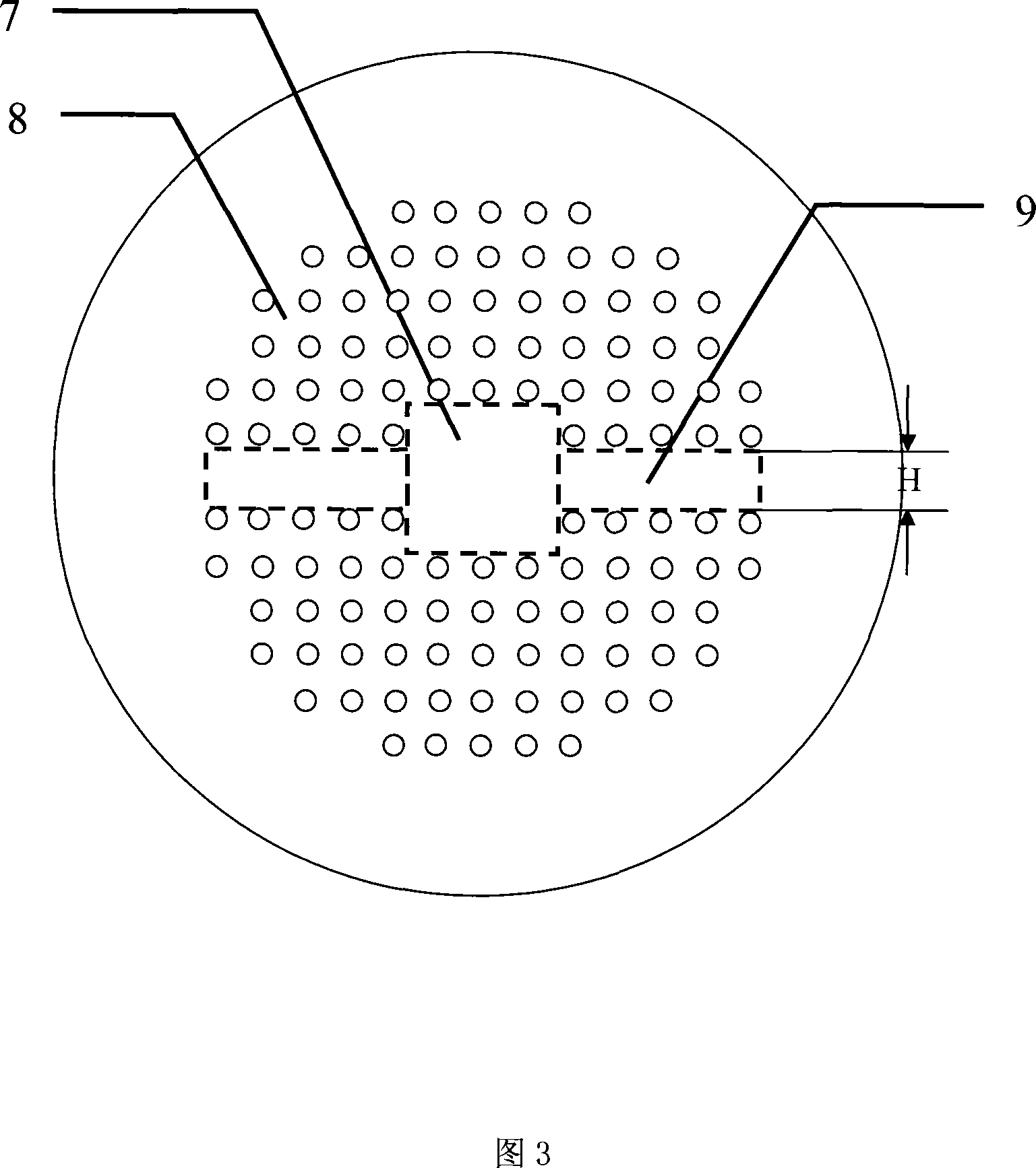
[0026]Embodiment 2: Symmetrical high equivalent refractive index linear region side leakage type square lattice polymer photonic crystal fiber, the cross-sectional structure is shown in Figure 3, it includes a perfluorinated polyethylene vinyl ether high refractive index core region 7 that transmits light waves And the cladding region 8 that surrounds the core region 7 and acts as a constraint on the transmitted light wave. The cladding region 8 is a low equivalent refractive index region formed by capillary pores parallel to the axial direction and arranged in a square lattice manner. The structural characteristics of the present invention are : There are two perfluorinated polyethylene vinyl ether high equivalent refractive index linear regions 9 parallel to the optical fiber core region 7 and extending outward from the core region 7 through the cladding region 8, and the perfluorinated polyethylene vinyl ether high equivalent The cross-sectional height H of the linear region...


PUM


Abstract

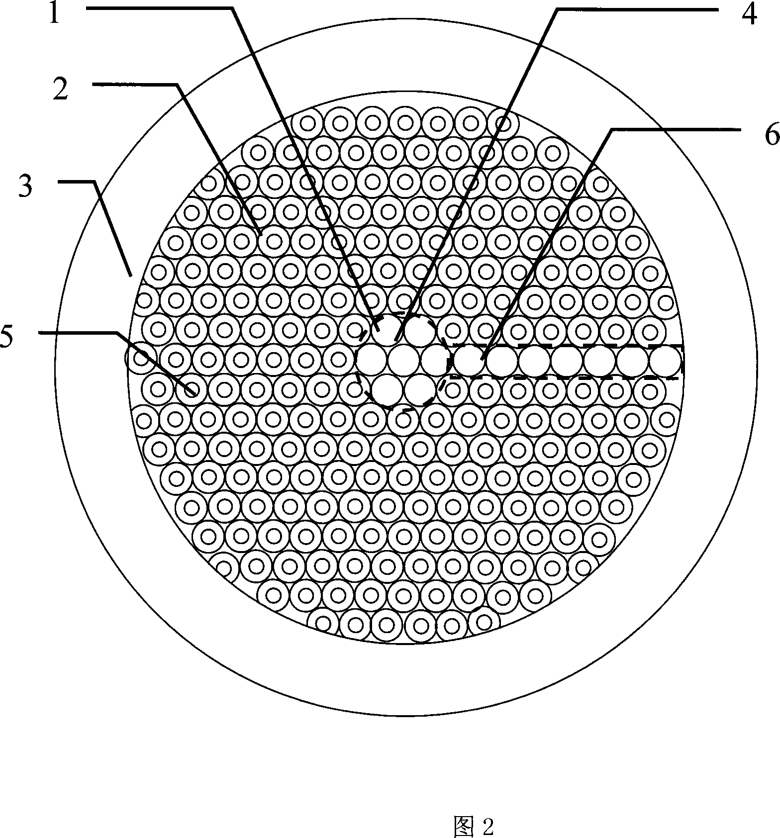
The invention is a side leakage photon crystal optical fiber, and its structure has one or two light wave high-equivalent refractivity linear regions extending outward from core region to pass through coating region and being parallel with the fiber core and having cross section height between half wavelength and wavelength of transmitted light, and its preparing method comprises the three steps of material selecting and processing, precast bar making, charging and wire drawing on wire drawing tower; the transmission losses of two vertical polarizing state of its guide mode have obviously difference, and it can use as single polarizing optical fiber itself and because of having stronger rotation sensitivity, it is suitable to small-rotating angle optical fiber sensing, and can be used for making standardized and automated production of high quality optical fiber couplers.

Description

technical field [0001] The invention relates to a side-leakage photonic crystal fiber and a preparation method thereof, in particular to the field of special optical fibers for optical fiber sensing. Background technique [0002] Since the photonic crystal fiber was born in 1996, new structures such as large numerical aperture, large mode field area, extremely small fundamental mode field area and high birefringence have been developed to meet various special needs. A typical photonic crystal fiber is a silica fiber or a polymer fiber. Air holes are periodically arranged in the cladding along the axial direction, and the fiber core is composed of an axial line defect that destroys the periodicity of its refractive index modulation. The existence of the air hole greatly expands the refractive index difference between the core and the cladding, provides a larger free space for the new structure design of the optical fiber, and provides a new possibility for controlling the tra...

Claims


Application Information

Patent Timeline
Patent Type & Authority Applications(China)
IPC IPC(8): G02B6/02G02B1/00C03B37/01
Inventor 娄淑琴方宏姚磊郭铁英李宏雷
Owner BEIJING JIAOTONG UNIV
Learn More