
Piezoelectric equipment with amplifying device

A technology of piezoelectric devices and piezoelectric materials, applied in the direction of piezoelectric devices/electrostrictive devices, etc., can solve problems such as reduced reliability performance, sensitive performance of inherent curvature devices, and equipment installation problems

Active Publication Date: 2007-08-22
ASM ASSEMBLY AUTOMATION LTD
View PDF3 Cites 3 Cited by
  • Summary
  • Abstract
  • Description
  • Claims
  • Application Information

AI Technical Summary

Problems solved by technology

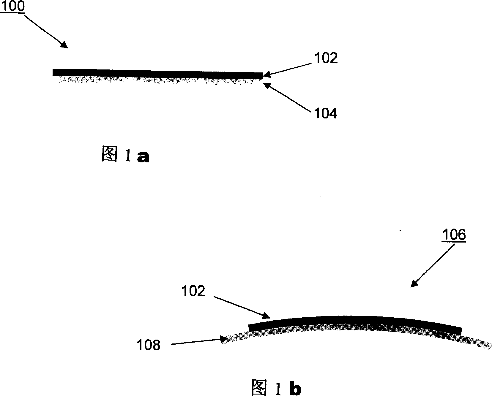
[0006] Although the derivative device 106 has better performance, due to its inherent curvature, the performance of the device performance is sensitive during installation, resulting in installation problems of the device
Due to the concentration of load on the curved surface of the device, the reliability performance of the device under operation is also reduced accordingly, which leads to the force concentration and friction on the piezoelectric ceramic layer
Therefore, if the device must be fitted with external objects, additional external components specifically designed for derivative devices are required

Method used


Image

  • Piezoelectric equipment with amplifying device
  • Piezoelectric equipment with amplifying device
  • Piezoelectric equipment with amplifying device

Examples


Embodiment Construction

[0022] Different embodiments of the piezoelectric device according to the present invention are described below with reference to the accompanying drawings, however, the present invention is not limited to these embodiments described in the accompanying drawings.

[0023] In the following description, the term "piezoelectric material" refers to those materials that can change their shape according to an electric signal and can generate an electric signal according to an applied load. These piezoelectric materials are preferably but not limited to piezoelectric ceramics, such as lead zirconate titanate (PZT), barium titanate (BaTiO 3 ), lead magnesium niobate-lead titanate (PMN-PT), and lead zirconium niobate-lead titanate (PZN-PT).

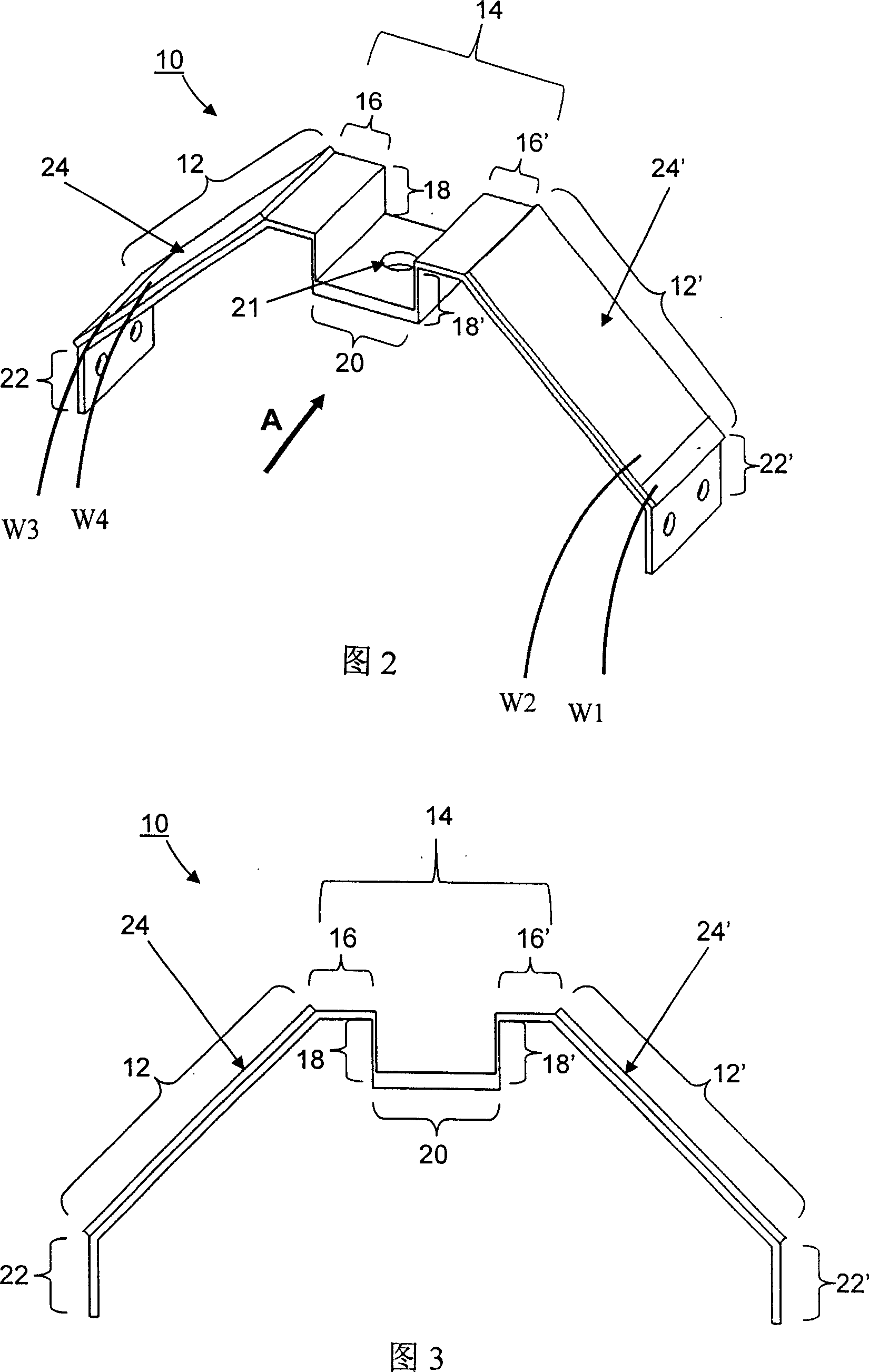
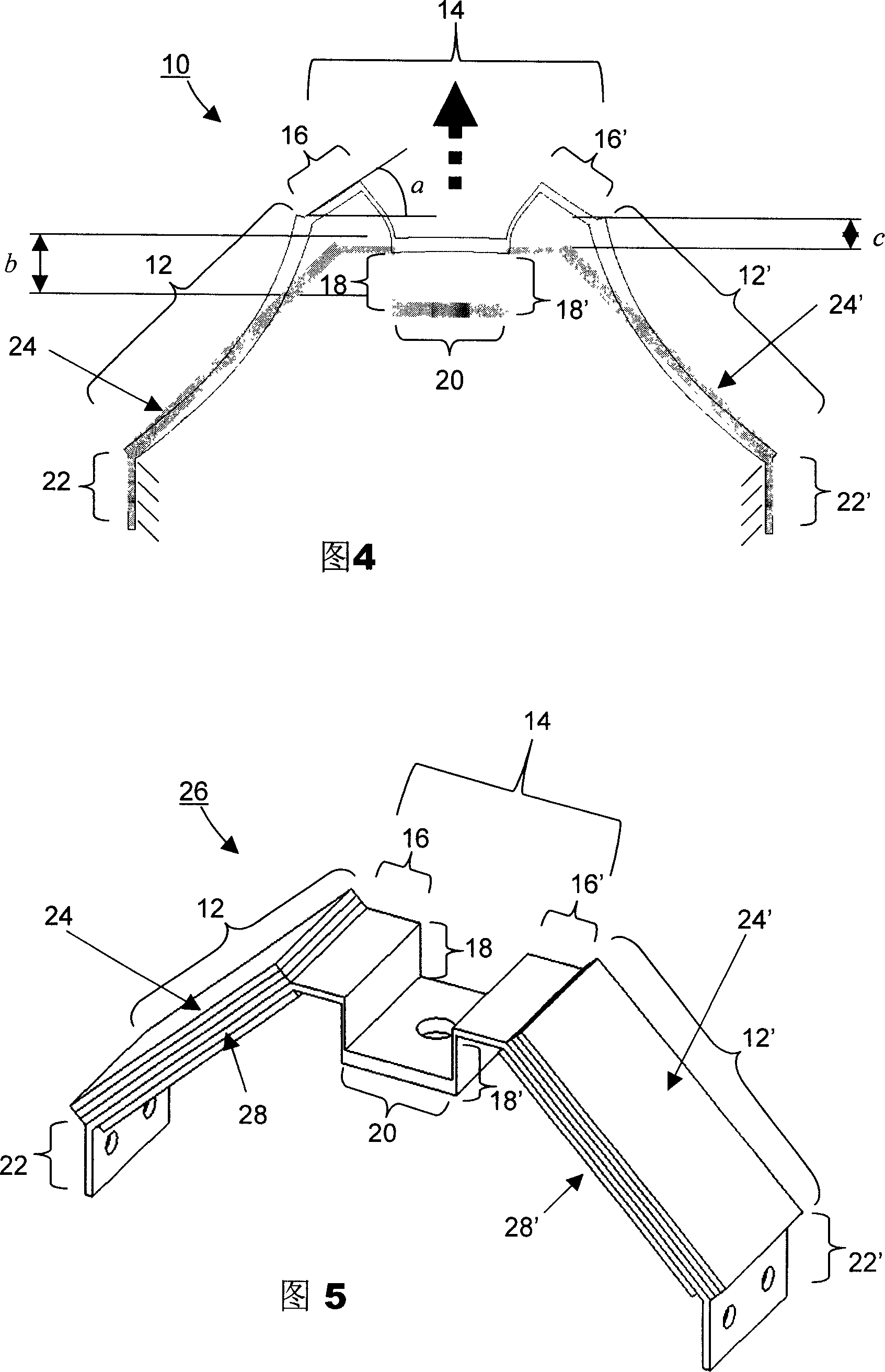
[0024] FIG. 2 is a schematic perspective view of the piezoelectric device 10 according to the first embodiment of the present invention. The piezoelectric device 10 has a saddle-like mechanical amplifier structure 14, and its driving part include...


PUM


Abstract

This invention discloses a piezoelectric device including: a mechanical amplifier for generating offset output and realizing action force input and a first and a second flexible platforms connected with the mechanical amplifier, in which, the first flexible platform is connected with one end of the amplifier, and the piezoelectric material fixed on the flexible platform is used in bending the first platform, the second platform is connected with the other end of the amplifier and the piezoelectric material fixed on the second platform bends it under control.

Description

technical field [0001] The present invention relates to piezoelectric devices, and more particularly to piezoelectric devices having a mechanical amplifier structure. The piezoelectric device is suitable for use in various devices such as actuators, force sensing and / or sensoriactuation. Background technique [0002] Drives are widely used in mechanical, electronic and optical systems, such as the positioning of telescope lenses, focusing of microscopes or vibration suppression of precision instruments. Traditional actuators relying on pneumatic, hydraulic, or electromagnetic forces cannot meet the needs of modern machinery in terms of response time, frequency, resolution, and shape. Accordingly, various types of actuators using piezoelectric, magnetostrictive, and shape memory alloy smart materials have been developed for these applications. [0003] The structure of these actuators is usually easily damaged and complex and expensive due to the large size, fragility and u...

Claims


Application Information

Patent Timeline
IPC IPC(8): H01L41/09
Inventor 柯少荣容忠尚陈王丽华蔡秉刚廖秋棋
Owner ASM ASSEMBLY AUTOMATION LTD
Learn More