Wire bonding method and apparatus

A wire bonding and bonding technology, applied in semiconductor devices, semiconductor/solid-state device manufacturing, non-electric welding equipment, etc., can solve problems such as increased idle time, limited accuracy, and PR positioning errors

Active Publication Date: 2007-08-29
ASM ASSEMBLY AUTOMATION LTD
View PDF0 Cites 3 Cited by
  • Summary
  • Abstract
  • Description
  • Claims
  • Application Information

AI Technical Summary

Problems solved by technology

[0008] Due to the limited bonding area, more frequent loading and unloading of substrates may be necessary, thus increasing free time for other processes, and this in turn directly affects UPH
Also, as the frequency of loading and unloading increases, operator attention needs to be more frequent
[0009] Another disadvantage is that hardware correction parameters are necessary for theta platform and camera to complete PR processing
Changes in LED device placement can lead to errors in PR positioning due to limited accuracy when using theta platforms

Method used


Image

  • Wire bonding method and apparatus
  • Wire bonding method and apparatus
  • Wire bonding method and apparatus

Examples


Embodiment Construction

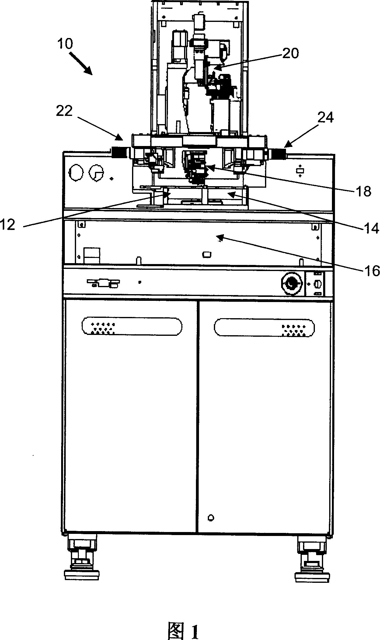
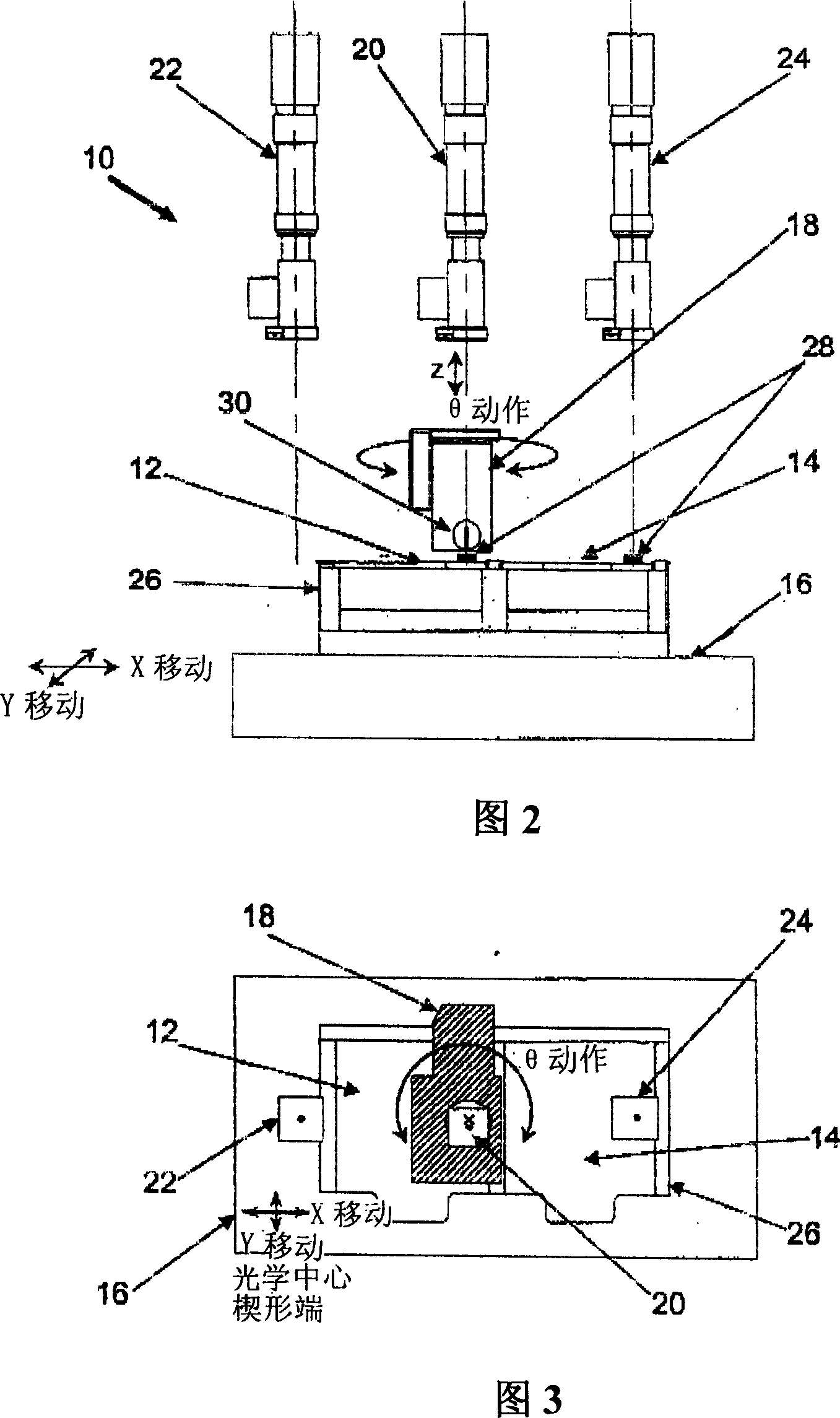
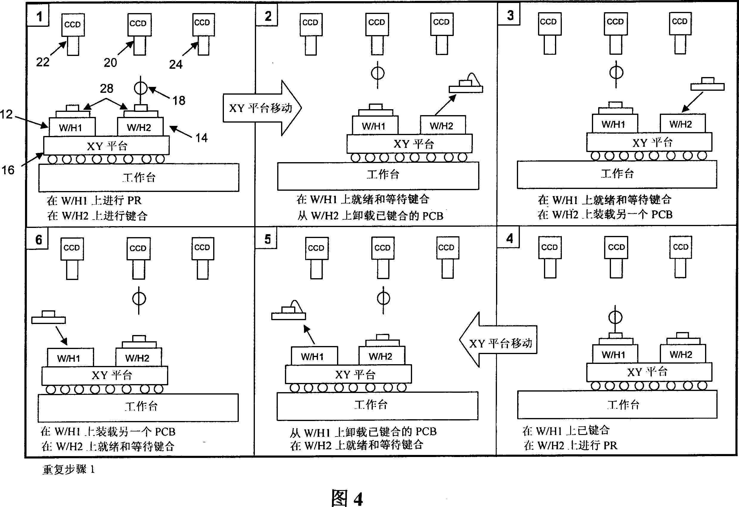
[0020] FIG. 1 is a schematic side view of a wire bonding machine 10 according to a preferred embodiment of the present invention. It generally includes: a double carrier, composed of a left carrier 12 and a right carrier 14; a positioning platform such as an XY platform, used to control the position of the double carriers 12, 14; a bonding head 18, used to complete wire bonding. The dual carrier 12 , 14 is mounted on an XY stage 16 .

[0021] There is also a first optical system such as left optical system 22 , a second optical system such as right optical system 24 and a third optical system such as central optical system 20 . These optical systems 20, 22, 24 preferably have built-in autofocus capability and adjustable magnification. The central optical system 20 is generally used to observe the bonding point and monitor the quality of the bonding wire before bonding, while the left optical system 22 and the right optical system 24 are set and arranged to observe the bonding...


PUM


Abstract

A wire bonding method and apparatus are provided for electronic components to enable PR processing and wire bonding to be carried out substantially concurrently. The apparatus comprises a bond head carrying a bonding tool for performing wire bonding and a rotary motor coupled to the bond head that is configured to change an angular orientation of the bonding tool relative to an electronic component to be bonded. There are first and second carriers for respectively mounting electronic components for wire bonding, and an optical system is arranged and configured to view bonding points on an electronic component mounted on the first carrier when the bonding tool is located over an electronic component mounted on the second carrier to perform wire bonding.

Description

technical field [0001] The present invention relates to wire bonding apparatus, and more particularly to a wire bonding apparatus for effecting wire connections between electronic components after the wire bonding points have been determined by visual inspection of the electronic components. Background technique [0002] Wire bonding is used in the semiconductor packaging industry to make electrical connections between electronic components, such as between a die and a substrate on which the die is mounted or between a die and another die. Generally, such wire bonding devices are classified into two types: ball bonding devices, in which solder balls are formed at the ends of wires to be bonded; wedge wire bonding devices, in which The wire is deformed during bonding. Wedge wire bonding setups take full advantage of wedge-shaped bonding tools. [0003] Ball bonding devices only require the bond head to move on three axes along the X, Y, and Z directions. But in the case of...

Claims


Application Information

Patent Timeline
Patent Type & Authority Applications(China)
IPC IPC(8): H01L21/60H01L21/68
CPCB23K20/004H01L2224/85H01L2924/01033H01L2924/01059H01L24/78H01L2924/01082B23K20/007H01L2924/00014H01L2924/01075H01L2224/78H01L24/85H01L2224/859H01L2224/48H01L2224/45099
Inventor 何永祥罗汉成林锦康
Owner ASM ASSEMBLY AUTOMATION LTD
Why Eureka
Try Eureka