Loop heat-conducting device

A loop and loop tube technology, applied in the field of heat conduction devices, can solve the problems of internal working fluid circulation failure, loop heat pipe drying up, and inability to provide working fluid backflow in a timely manner, so as to overcome the reverse gravity operation, improve capillary force, and optimize The effect of cooling efficiency

Inactive Publication Date: 2007-08-29
YEH CHIANG TECH CORP
View PDF0 Cites 29 Cited by
  • Summary
  • Abstract
  • Description
  • Claims
  • Application Information

AI Technical Summary

Problems solved by technology

If the flow caused by the input heat exceeds the capillary limit, the compensation chamber 1a' cannot provide the return flow of the working fluid in a timely manner, the loop heat pipe will dry out, and the circulation of the internal working fluid will fail

Method used


Image

  • Loop heat-conducting device
  • Loop heat-conducting device
  • Loop heat-conducting device

Examples


Embodiment Construction

[0019] The technical characteristics of the present invention will be further described in conjunction with the following examples. These examples are only examples of preferred representatives, and are not intended to limit the scope of the present invention. The best understanding of the present invention is obtained by referring to the accompanying drawings in conjunction with the following detailed description.

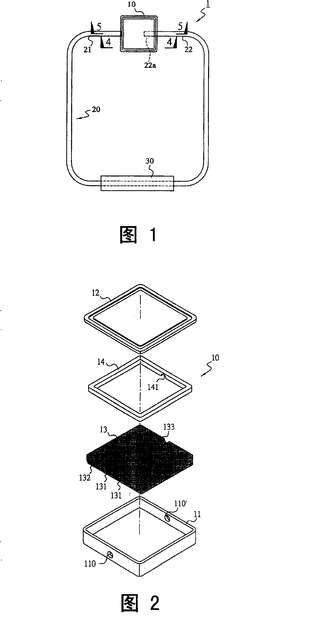
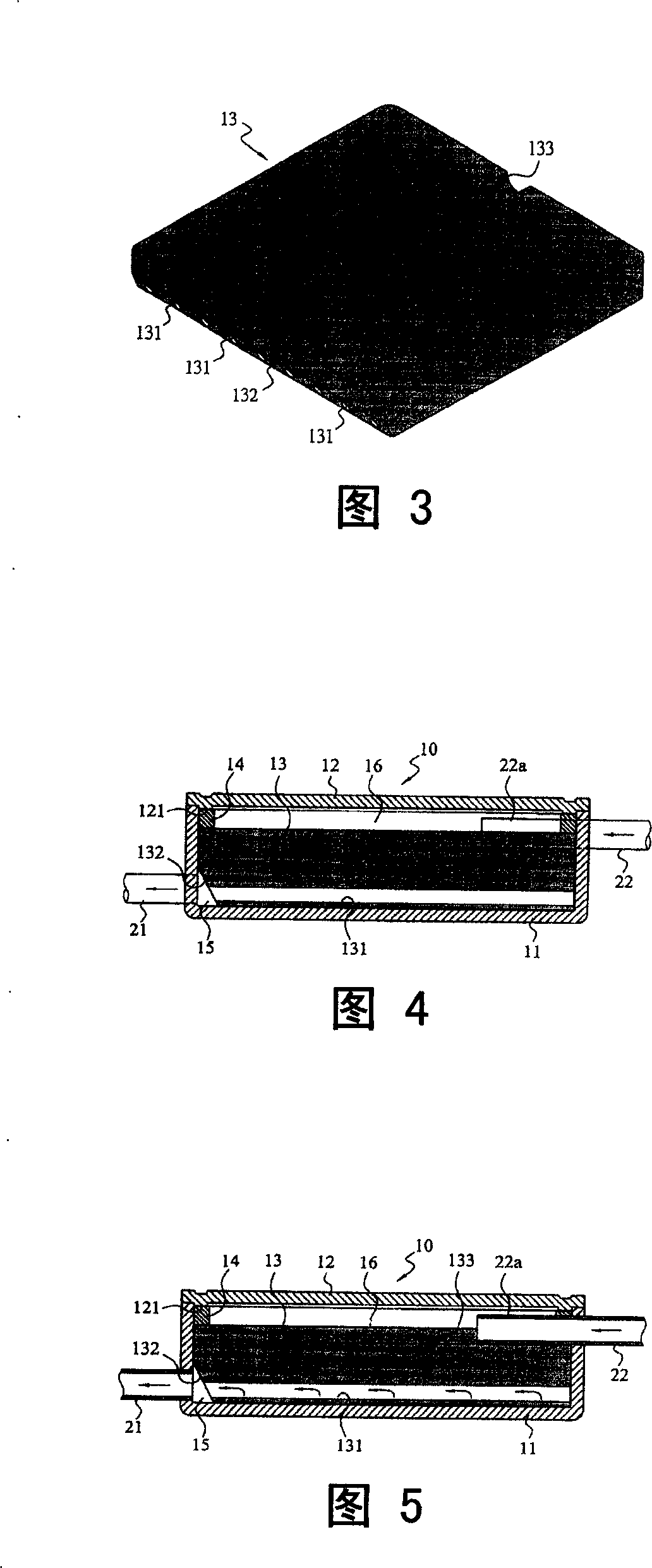
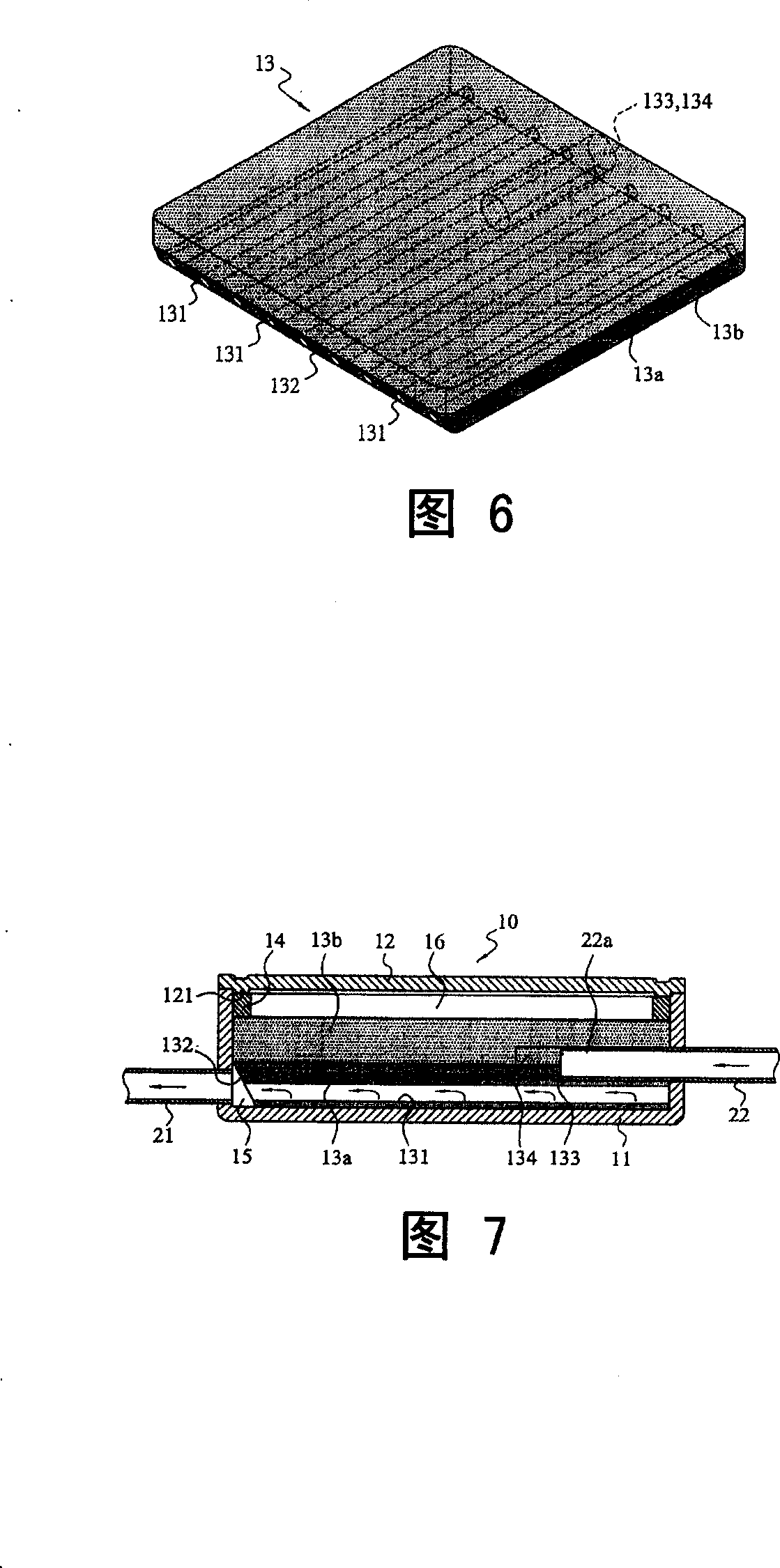
[0020] First, referring to Fig. 1 to Fig. 5, it is an embodiment of the loop heat conduction device 1 of the present invention, as shown in Fig. 1, it basically includes an evaporator 10 and a condenser 30, and a loop pipe 20 is passed between the two. Connected to form a circulation loop of the fluid working medium. FIG. 2 is an exploded perspective view of the evaporator 10 of the present invention. FIG. 3 is a perspective view of the first embodiment of the capillary tissue core 13 of the present invention. 4 and 5 are cross-sectional views of the capillary st...


PUM


Abstract

The loop heat conducting equipment includes vaporizer and condenser connected to each other through circle pipe so as to constitute circulation loop of liquid working medium. The vaporizer possesses core body of capillary structure (CBCS) inside. Multiple tunnels are formed in CBCS. One end of tunnels is converged to vapor chamber, which is connected to one end of the circle pipe to form the output end of gas state working medium. After through the condenser, the other end of the circle pipe as the input end of formed liquid working medium is connected to the vaporizer. Extending into and contacting with inner CBCS, end of the circle pipe forms compensated chamber of liquid working medium on up portion of CBCS. Using gas and liquid separated circulation loop, the invention reaches optimal efficiency of heat elimination. Features are: simple structure, and easy of measure yield.

Description

technical field [0001] The invention relates to a heat conduction device, in particular to a loop heat conduction device. The evaporator and the condenser are connected through a ring pipe to form a circulation circuit of a fluid working medium. The evaporator is provided with a steam chamber and a compensation chamber. liquid separation to achieve the best heat dissipation efficiency. Background technique [0002] With the rapid development of technology and the rapid development of electronic products, under the trend of lightness, thinness, shortness, smallness and refinement, and the requirements for performance are getting higher and higher, the corresponding power used must be higher and higher. In this way, as the volume becomes smaller and the power becomes larger, the heating density on the surface of the electronic components will increase rapidly, and the corresponding heat treatment problem will become very difficult. The heat accumulation effect in high-power c...

Claims


Application Information

Patent Timeline
Patent Type & Authority Applications(China)
IPC IPC(8): H05K7/20H01L23/427G06F1/20G12B15/02
Inventor 金积德王志圣涂堂烘
Owner YEH CHIANG TECH CORP
Why Eureka
Try Eureka