Satellite scanning radar scatterometer

A scanning radar and scatterometer technology, applied in the direction of reflection/re-radiation of radio waves, utilization of re-radiation, radio wave measurement systems, etc. rate sweep measurement, the effect of reducing requirements

Inactive Publication Date: 2007-09-05
NAT SPACE SCI CENT CAS
View PDF0 Cites 8 Cited by
  • Summary
  • Abstract
  • Description
  • Claims
  • Application Information

AI Technical Summary

Problems solved by technology

If the orbit height is increased from 800km to 960km, to maintain a resolution of 50km, the beam width should be reduced to 1.2~1.3 degrees, and the scanning speed should be increased to about 20rpm. If the system of transmitting and receiving the same beam is adopted, the scanning loss will increase to 10 ~12dB

Method used


Image

  • Satellite scanning radar scatterometer
  • Satellite scanning radar scatterometer
  • Satellite scanning radar scatterometer

Examples


Embodiment Construction

[0044] Below in conjunction with accompanying drawing and specific embodiment the present invention is described in further detail:

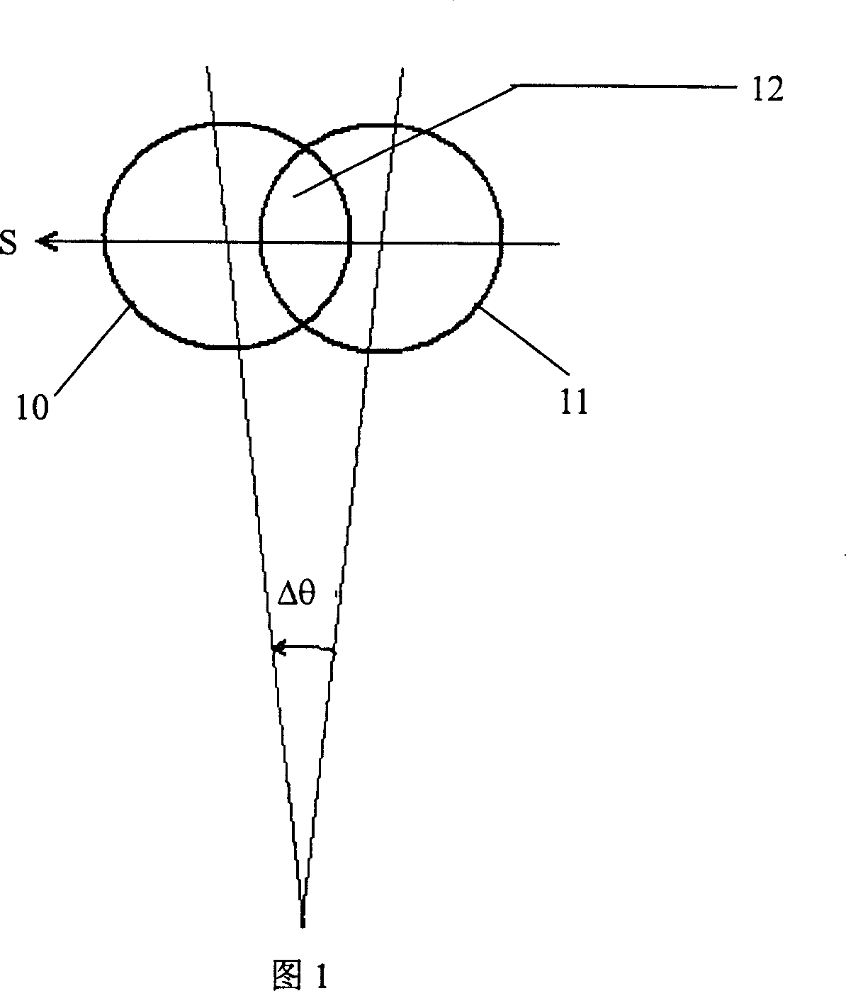
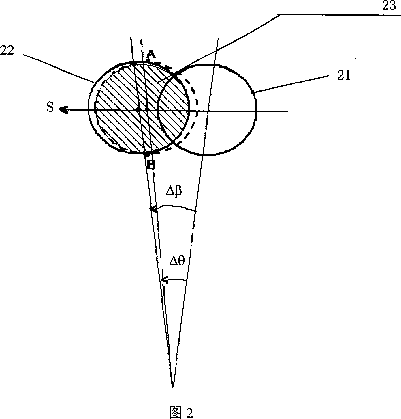
[0045]In order to facilitate understanding of the present invention, Fig. 2 shows the schematic diagram of the principle of the compensation method proposed by the present invention, the direction S in the figure represents the beam scanning direction, the angle Δβ is the included angle along the scanning direction between the receiving beam and the transmitting antenna beam, and the angle Δθ Indicates the scanning offset of the antenna beam pointing, the number 21 indicates the ground footprint of the receiving antenna at the time of transmission, the number 22 indicates the ground footprint of the transmitting antenna at the time of transmission, and the number 23 indicates the ground footprint of the receiving antenna at the time of reception. when

[0046] When Δβ=Δθ (7), the offset loss caused by beam scanning can be fully compensated: when...


PUM


Abstract

A scatter meter being set with transceiver double wave-beam antenna and being used on radar carried by satellite consists of support, the first feed and the second feed. It is feature as connecting two said feeds separately to an emitter and a receiver, configuring wave beam of receiving antenna on the first feed to be in certain included angle with wave beam of emitting antenna on the second feed.

Description

technical field [0001] The invention relates to a radar scatterometer, in particular to a spaceborne scanning radar scatterometer with a transmitting and receiving double-beam antenna. Background technique [0002] Spaceborne radar is an important instrument for earth observation. It is a common measurement method to measure and image targets within the observation swath by scanning the radar antenna beam. In the prior art, the distance between the radar antenna and the observed target or area causes a certain delay between the arrival time of the target echo signal received by the radar and the time when the radar transmits the signal. After this delay, the beam direction or irradiation area of ​​the scanning radar antenna will deviate, that is, the footprint of the radar beam on the ground or sea at the time of transmission will deviate from the footprint of the radar beam at the time of reception. As shown in Figure 1, the direction S represents the beam scanning directi...

Claims


Application Information

Patent Timeline
Patent Type & Authority Applications(China)
IPC IPC(8): G01S7/28G01S13/90
Inventor 董晓龙孙波陈天辰刘和光
Owner NAT SPACE SCI CENT CAS
Why Eureka
Try Eureka