Mixer

A technology of mixer and mixed signal, which is applied in the direction of modulation transformation balance device, etc., can solve the problems of small operating range, power consumption, dead zone, etc., and achieve the goal of avoiding dead zone phenomenon, reducing power consumption and reducing current value Effect

Active Publication Date: 2007-09-05
VIA TECH INC
View PDF0 Cites 5 Cited by
  • Summary
  • Abstract
  • Description
  • Claims
  • Application Information

AI Technical Summary

Problems solved by technology

If the power supply V dd If the remaining voltage V' is too small, it will affect the operation area of ​​the BJT differential pair circuit 11 and the transistors of the current switching circuit 12, so that the fundamental frequency current signal on IF+, IF- is affected by the load circuit 13 instead of being affected by the radio frequency signal The impact on RF+ and RF- is still greater, resulting in the phenomenon of dead zone (deadzone)
[0008] In addition, the basic frequency current signal to IF+, IF- is limited by the range of the voltage value of the load circuit 13, so that the basic frequency current signal to IF+, IF- has a small operating range and is output in a non-linear manner; The special mixer 1 needs to use a large supply current I, so the power consumption is serious

Method used


Image

  • Mixer
  • Mixer
  • Mixer

Examples


Embodiment Construction

[0057] A mixer according to a preferred embodiment of the present invention will be described below with reference to related drawings, wherein the same components will be described with the same reference symbols.

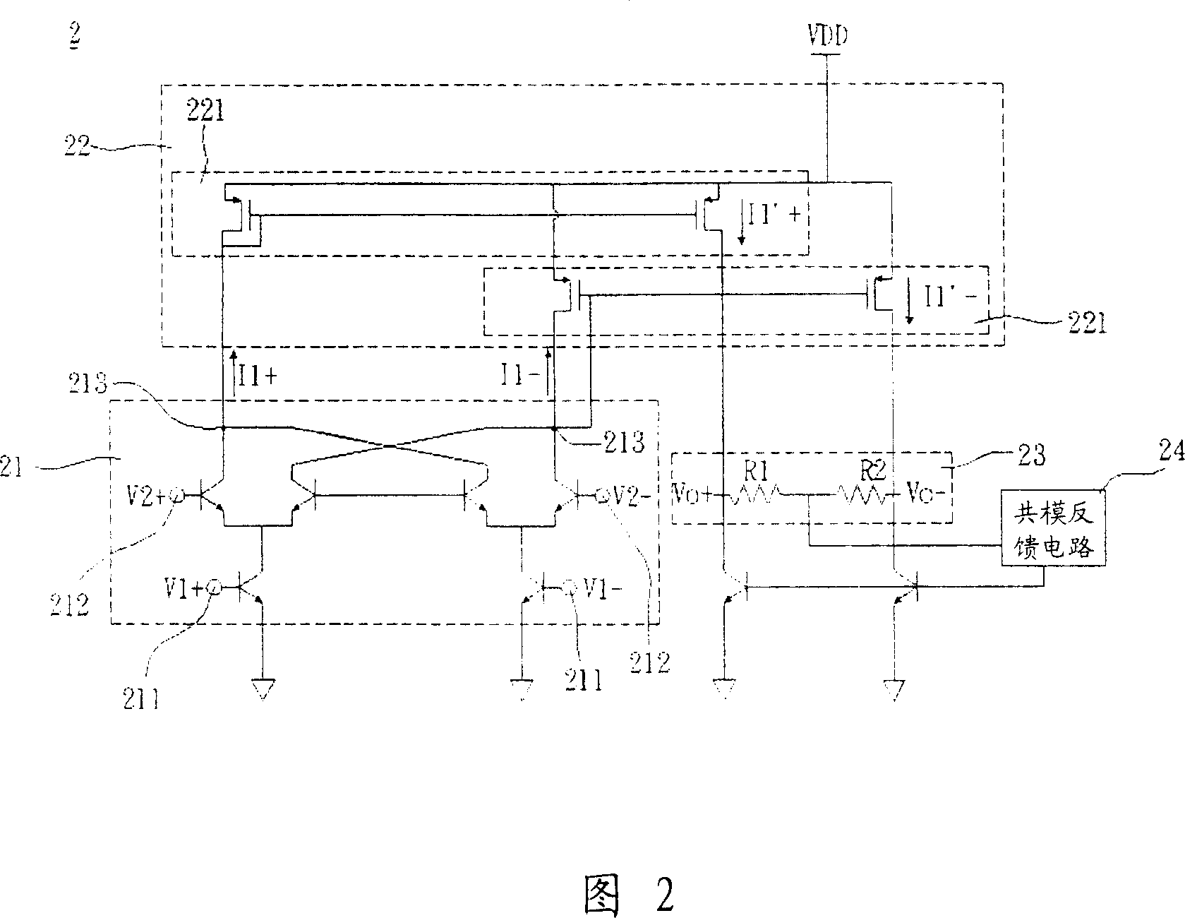
[0058] Please refer to FIG. 2 , the mixer 2 of the first embodiment of the present invention includes a mixing circuit 21 , a replicating circuit 22 and a load circuit 23 . Wherein, the mixer 2 of this embodiment may be a direct down-conversion mixer.

[0059] The hybrid circuit 21 of this embodiment includes a first differential input terminal 211, a second differential input terminal 212 and a differential output terminal 213, and the first differential input terminal 211 and the second differential input terminal 212 are respectively Receive a first input signal pair V1+, V1- and a second input signal pair V2+, V2-, and the mixing circuit 21 mixes the first input signal pair V1+, V1- and the second input signal pair V2+, V2-, to Output a mixed signal pair I1+,...


PUM


Abstract

A conversion mixer includes a mixing circuit, a duplicating circuit and a loading circuit. The mixing circuit receives a couple of first input signals and a couple of second input signals and mixes the couple of first input signals with the couple of second input signals to output a couple of mixed signals. The duplicating circuit coupled to the mixing circuit receives the couple of mixed signals and duplicates the couple of mixed signals to output a couple of duplicated signals. The loading circuit coupled to the duplicating circuit receives the couple of duplicated signals and outputs a couple of output signals according to the couple of duplicated signals.

Description

technical field [0001] The invention relates to a mixer, in particular to a mixer for converting a high-frequency input signal into a low-frequency output signal. Background technique [0002] In the microwave communication technology, since the radio frequency (RF) signal in the transceiver is difficult to process, the received radio frequency signal is modulated and downconverted to the base frequency signal to facilitate subsequent signal processing. [0003] Most of the current practice is to add a mixer to the RF front-end circuit (RF Front-End) in the transceiver, and use the mixer to mix and modulate the RF signal and the local oscillator signal to generate a new intermediate signal . In addition, the mixer also controls important parameters such as the noise figure (Noise Figure), isolation (Isolation), 1dB compression point (1dB Compression Point) and third-order interactive modulation point (IP3) of the transceiver circuit, so the mixer is in the It occupies a ve...

Claims


Application Information

Patent Timeline
IPC IPC(8): H03D7/14
Inventor 林陈庆曾英哲
Owner VIA TECH INC
Why Eureka
Try Eureka