
Power steering system

一种动力转向装置、动力缸的技术,应用在动力转向机构、转向机构、流体转向机构等方向,能够解决产生噪声、浪涌或水击作用等问题,达到防止振动向手柄的传递、防止噪声的发生、提高操舵感的效果

Inactive Publication Date: 2007-09-12
HITACHI LTD
View PDF1 Cites 4 Cited by
  • Summary
  • Abstract
  • Description
  • Claims
  • Application Information

AI Technical Summary

Problems solved by technology

At this time, if the rudder speed at which the driver switches back to the steering wheel exceeds a given value, the flow of working oil flowing from the power-assisted side (high-pressure side) to the non-power-assisted side (low-pressure side) becomes excessive, and the excess working oil Flow through the back pressure valve set in the pump, so that the fluid phenomenon such as surge or water hammer is transiently generated, and noise is generated

Method used


Image

  • Power steering system
  • Power steering system
  • Power steering system

Examples


Embodiment Construction

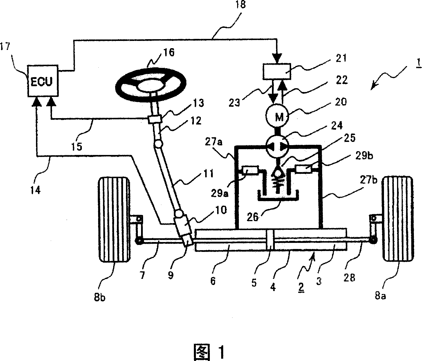
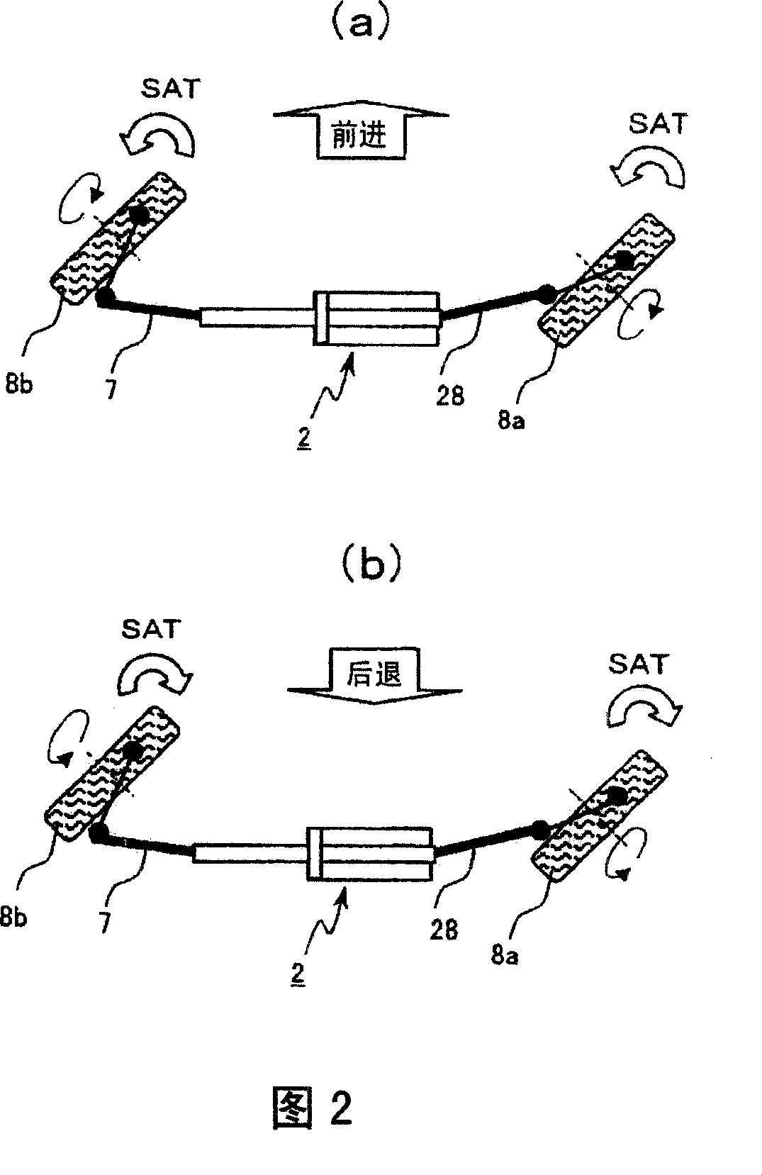
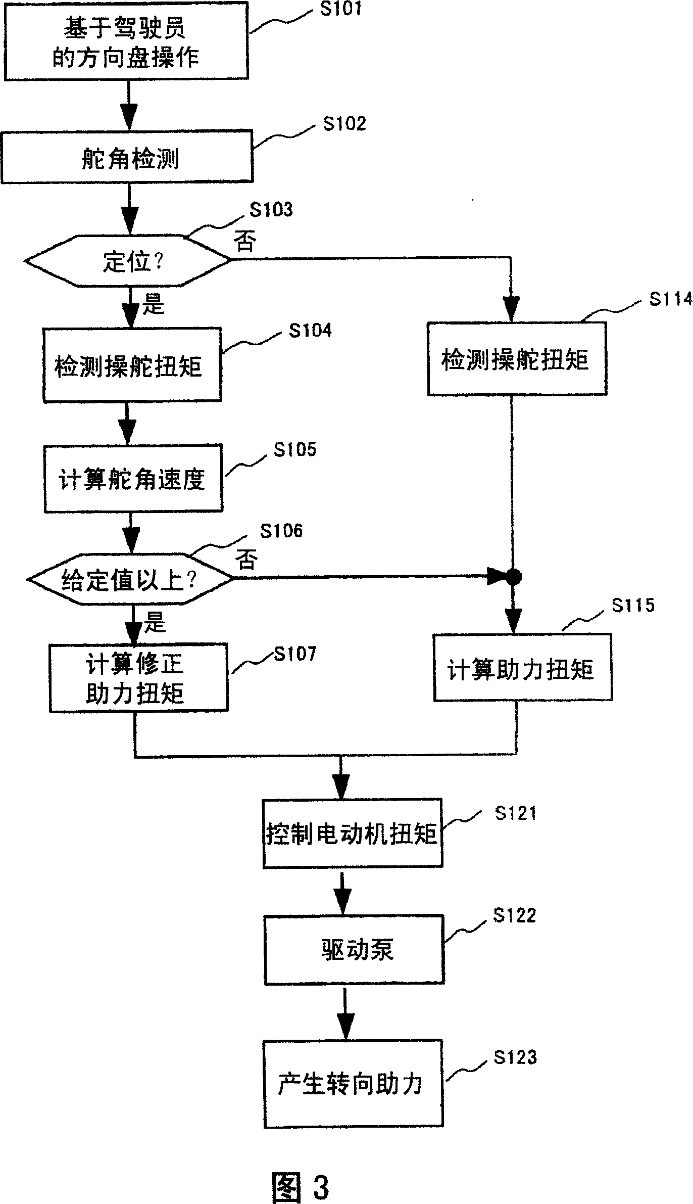
[0028] A power steering device according to an embodiment of the present invention will be described in detail below with reference to FIGS. 1 to 12 . 1 to 9 are diagrams illustrating a power steering apparatus according to Embodiment 1 of the present invention, and FIG. 10 is a diagram illustrating a power steering apparatus according to Embodiment 2 of the present invention. FIG. 11 is a diagram illustrating excess flow of hydraulic oil from the high-pressure side oil passage to the low-pressure side oil passage when the cut-in state of the steering mechanism of the power steering device according to the present embodiment ends and transitions to return. FIG. 12 is a schematic diagram illustrating a problem to be solved and a solution of the power steering device according to the embodiment of the present invention.

[0029] FIG. 1 is a diagram showing an overall configuration of a power steering apparatus according to Embodiment 1 and Embodiment 2 of the present invention. ...


PUM


Abstract

In a power steering system comprising a power cylinder for assisting a steering power of a steering mechanism, a hydraulic pump for supplying a hydraulic pressure to the power cylinder, a first oil passage and a second oil passage connecting the power cylinder and the hydraulic pump respectively, a motor for driving the hydraulic pump, and power steering control means for calculating a command value to the motor based on the steering torque, a flow rate of the working oil supplied from a high-pressure side oil passage to a low-pressure side oil passage is restrained at the transition from the end of the steering state (lock end) of the steering mechanism to the returning. The flow-rate restraint increasingly corrects a driving current of the motor in the steering direction or limits the flow rate of the working oil.

Description

technical field [0001] The present invention relates to a power steering system for steering assist of wheels, and to a control device for a motor for improving steering feeling when a steering wheel is positioned. Background technique [0002] A hydraulic mechanism is generally used as a booster that assists the steering force of the wheels according to the steering torque input from the driver. As an example of the prior art, it is proposed that an oil pump is driven by an electric motor to generate hydraulic pressure, and a steering torque input from a steering wheel is fed back to the generated hydraulic pressure to generate steering assist force (see Patent Document 1). In the conventional technique disclosed in Patent Document 1, a steering torque is detected from a value of a torque sensor, a steering boost corresponding to the torque is generated, and pressure supplied to a hydraulic cylinder is controlled. [0003] [Patent Document 1] JP-A-2003-212141. [0004] Ho...

Claims


Application Information

Patent Timeline
Patent Type & Authority Applications(China)
IPC IPC(8): B62D5/065
CPCB62D5/065
Inventor 宫岛步坪野勇西垣户贵臣高桥哲佐佐木光雄榊敏光松村达雄
Owner HITACHI LTD
Learn More