Components having sharpen waveguide y-y-branches angle

A device and waveguide technology, applied in the field of circuit manufacturing, can solve problems such as limiting the optical performance of devices

Inactive Publication Date: 2007-09-12
INTEL CORP
View PDF1 Cites 3 Cited by
  • Summary
  • Abstract
  • Description
  • Claims
  • Application Information

AI Technical Summary

Problems solved by technology

Furthermore, due to the wave nature of light used in photolithographic methods and the surface tension of photoresists during exposure and development, the resulting edges are rounded, which limits the optical performance of some devices

Method used


Image

  • Components having sharpen waveguide y-y-branches angle
  • Components having sharpen waveguide y-y-branches angle
  • Components having sharpen waveguide y-y-branches angle

Examples


Embodiment Construction

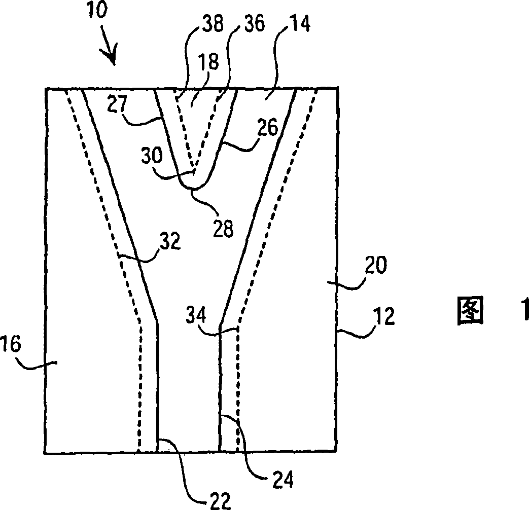
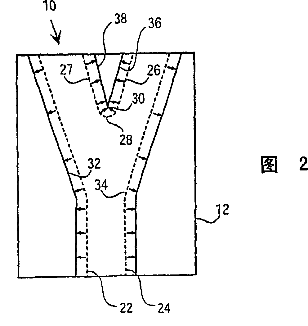
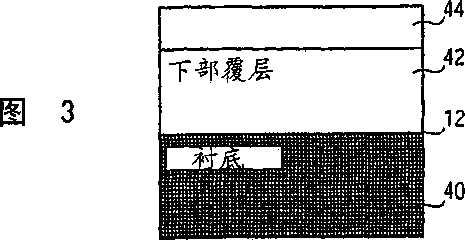
[0016] Embodiments of fabrication methods for sharpening corners (eg, corners at Y-branches) in integrated optics and other microdevices will be described herein. In the following description, numerous specific details are given in order to provide a thorough understanding of embodiments of the invention. However, one skilled in the art will understand that the invention may be practiced without one or more of the specific details, or with other methods, components, materials, etc. In other instances, well-known structures, materials, or operations are not shown or described in detail so as not to obscure aspects of the invention.

[0017] Reference throughout this specification to "one embodiment" or "an embodiment" means that a feature, structure, or characteristic described in connection with the embodiment is included in at least one embodiment of the present invention. The phrases "in one embodiment" or "in an embodiment" may appear in various places throughout the speci...


PUM


Abstract

Substantially sharp corners for optical waveguides in integrated optical devices, photonic crystal devices, or for micro-devices, can be fabricated. Non-sharp corners such as rounded corners, are first formed using lithographic patterning and vertical etching. Next, isotropic etching is used to sharpen the rounded corners. A monitor can be used to determine if the rounded corners have been sufficiently sharpened by the isotropic etching.

Description

[0001] This application is a divisional application of Chinese patent application 02807043.7 (PCT / US02 / 02285), and the filing date of the original application is January 25, 2002. technical field [0002] The disclosure herein relates generally to circuit fabrication, and particularly, but not exclusively, to devices including corners in a Y-leg that are sharpened, such as those of integrated optics, photonic crystal devices, and other microdevices. Background technique [0003] Integrated optics, such as those formed on planar lightwave circuit chips, typically include optical components in the form of optical waveguides. In fact, optical waveguides are often the fundamental components of all integrated optics. Optical waveguides are used to guide optical signals from one location to another, and are often bifurcated or "split" at different locations to allow the optical signal to be passed to several different locations. A "Y-branch" splitter configuration for an optical ...

Claims


Application Information

Patent Timeline
Patent Type & Authority Applications(China)
IPC IPC(8): G02B6/125G02B6/136G02B6/12
CPCG02B2006/1213G02B6/136G02B6/125
Inventor X·王F·莱昂
Owner INTEL CORP
Why Eureka
Try Eureka