Self-aligning roller bearing with retainer and method of manufacturing the retainer for the self-aligning roller bearing

A self-aligning, roller bearing technology, applied in the direction of roller bearings, rolling contact bearings, bearing components, etc., to achieve the effects of suppressing deflection, increasing flow, and suppressing cost increases

Active Publication Date: 2007-09-12
NSK LTD
View PDF1 Cites 12 Cited by
  • Summary
  • Abstract
  • Description
  • Claims
  • Application Information

AI Technical Summary

Problems solved by technology

Therefore, the cage mounted on the self-aligning roller bea...

Method used


Image

  • Self-aligning roller bearing with retainer and method of manufacturing the retainer for the self-aligning roller bearing
  • Self-aligning roller bearing with retainer and method of manufacturing the retainer for the self-aligning roller bearing
  • Self-aligning roller bearing with retainer and method of manufacturing the retainer for the self-aligning roller bearing

Examples


Embodiment Construction

[0082] First example of embodiment

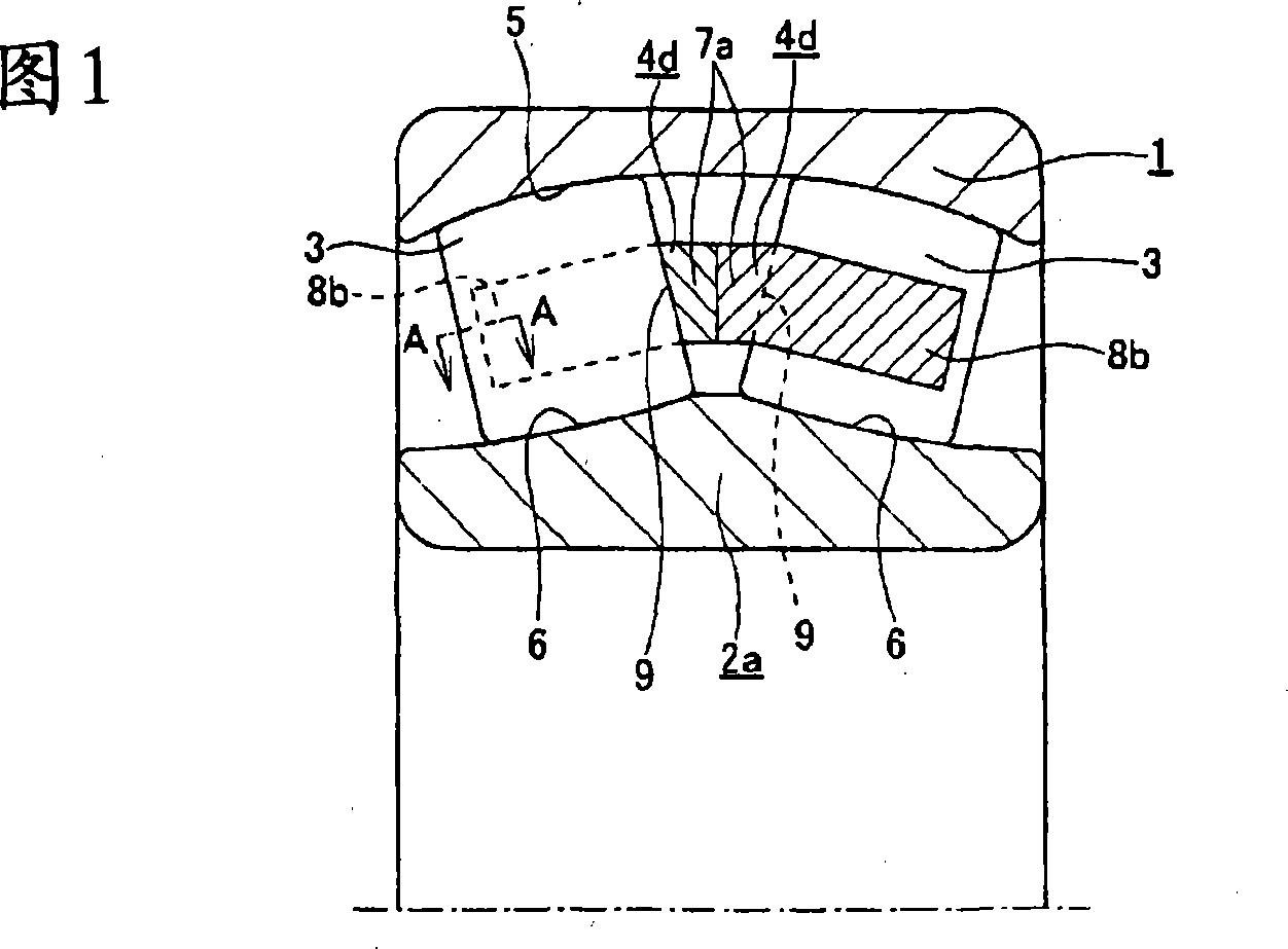
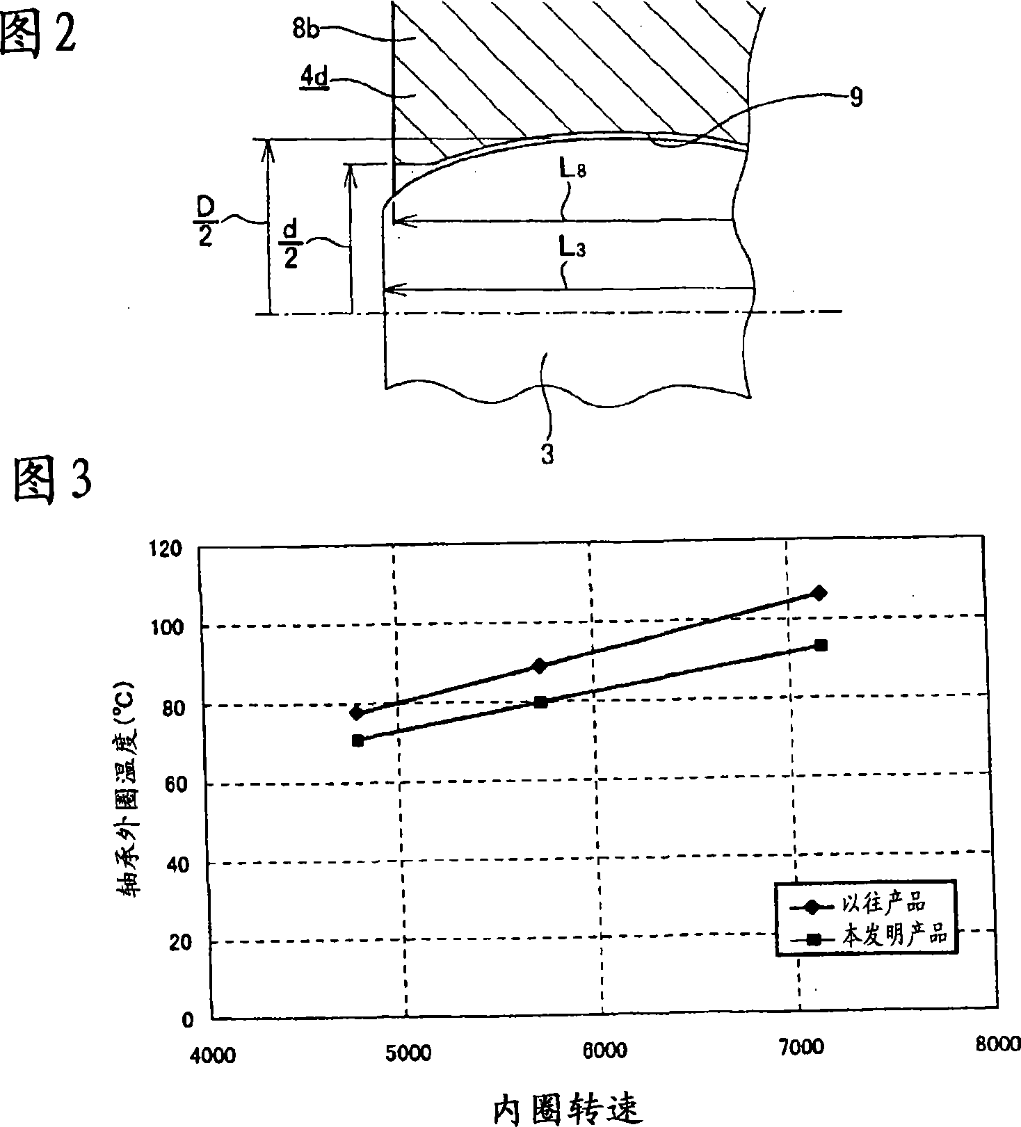
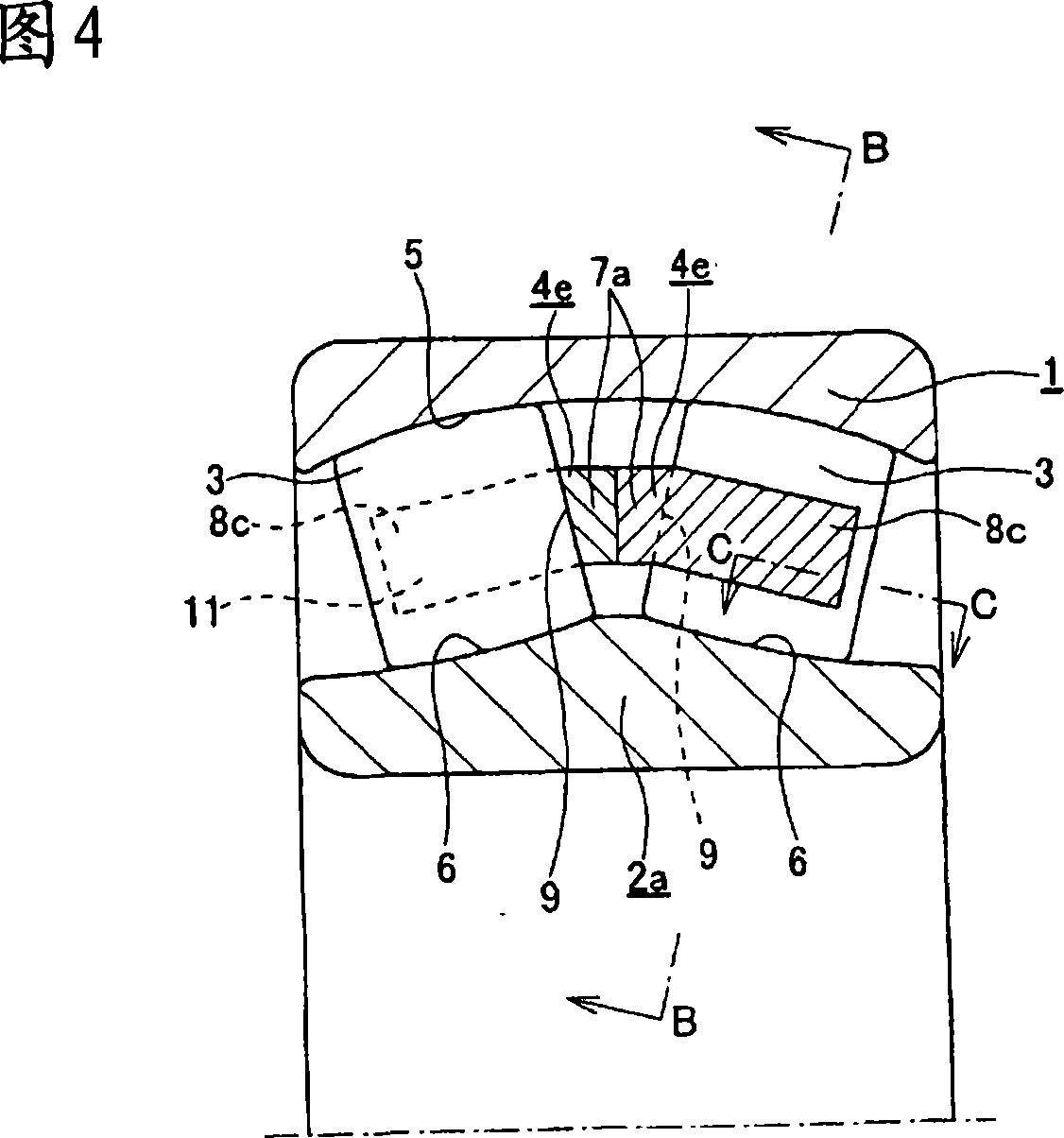
[0083] 1 and 2 show a first example of an embodiment of the present invention corresponding to the first aspect. The self-aligning roller bearing with cage in this example is the same as the second example of the existing structure shown in Fig. A pair of holders 4d that can be combined in a relatively rotatable manner.

[0084] Among them, the outer ring 1 has an outer ring rail 5 having a single central spherical concave surface formed on its inner peripheral surface.

[0085] In addition, the inner ring 2 a has a pair of inner ring rails 6 facing the outer ring rails 5 formed on its outer peripheral surface. This inner ring 2a is different from the case of the second example of the above-mentioned conventional structure in that the flange portions 10 are not provided on the outer peripheral surfaces of both ends (see FIG. 20 ). The inner ring 2a incorporated in this example has the same shape as that of the third example of the conven...


PUM


Abstract

There is realized a self-aligning roller bearing with retainer that stabilizes the orientation of spherical rollers and prevents these spherical rollers from skewing, and which can be rotated at high speed, and furthermore which enables efficient lubricant feed into pockets 9. By rotating a turning tool 14 as it revolves, the surfaces on both sides in the circumferential direction of respective column sections are processed into concave curved surfaces that oppose a rolling surface of the respective spherical rollers across a pocket clearance into which lubricant oil can be fed. The length of the column sections 8c is less than the length in the axial direction of the spherical rollers, and greater than a half of the length, and an end portion of the side surface in the circumferential direction of the respective column sections 8c projects further in the circumferential direction than an intermediate portion thereof, and the spherical rollers are embraced in the pockets 9.A self-aligning roller bearing with a retainer enabling high speed operation by stabilizing the attitude of barrel shaped rollers to prevent the barrel shaped rollers from being skewed and the efficient feeding of a lubricant into pockets (9) and a method of manufacturing the retainer for the self-aligning roller bearing. In the self-aligning roller bearing, the both side faces of each column part (8c) in the circumferential direction are machined to recessed curved faces facing the rolling surface of each barrel shaped roller through pocket clearances allowing the lubricant to feed thereto with a cutting tool (14) revolving while rotating on its axis. Also, the length of each column part (8c) is set equal to or less than the axial length of each barrel shaped roller and more than the half of the axial length thereof, the side face tip portion of each column part (8c) in the circumferential direction are projected from the intermediate portion thereof in the circumferential direction.

Description

technical field [0001] The self-aligning roller bearing with a cage of the present invention is assembled on a rotary supporting part such as a drum of various industrial machinery such as a papermaking machine and a metal rolling mill in order to support a rotating shaft inside a housing, for example. status for use. Background technique [0002] For example, in order to freely rotatably support a heavy shaft inside the housing, conventionally, for example, those described in JP-A-9-317760 (Patent Document 1) and Utility Model Registration No. 2524932 (Patent Document 2) are used. Self-aligning roller bearings with cage. 16 to 19 show a first example of the conventional structure described in Patent Document 1. As shown in FIG. In this self-aligning roller bearing with a cage, a plurality of spherical rollers 3 are arranged to roll freely between an outer ring 1 and an inner ring 2 which are combined concentrically with each other. And, the posture and position of these ...

Claims


Application Information

Patent Timeline
IPC IPC(8): F16C33/48F16C19/38F16C23/06F16C33/49F16C33/66
Inventor 村井隆司田中利幸市丸雅丈
Owner NSK LTD
Why Eureka
Try Eureka