Ultrasonographic device and ultrasonographic device control method

A diagnostic device and ultrasonic technology, applied in the directions of sonic diagnosis, infrasonic diagnosis, ultrasonic/sonic/infrasonic diagnosis, etc., can solve the problems of elastic characteristics fluctuation, difficulty in judging whether the measurement result is a correct value, etc., to improve reliability and easy The effect of watching

Inactive Publication Date: 2007-09-19
PANASONIC CORP
View PDF1 Cites 5 Cited by
  • Summary
  • Abstract
  • Description
  • Claims
  • Application Information

AI Technical Summary

Problems solved by technology

Due to these reasons, the obtained elastic properties may vary, and it is difficult to judge whether the measurement results are correct values.

Method used


Image

  • Ultrasonographic device and ultrasonographic device control method
  • Ultrasonographic device and ultrasonographic device control method
  • Ultrasonographic device and ultrasonographic device control method

Examples


no. 1 Embodiment approach

Next, a first embodiment of an ultrasonic diagnostic apparatus according to the present invention will be described.

[0053]

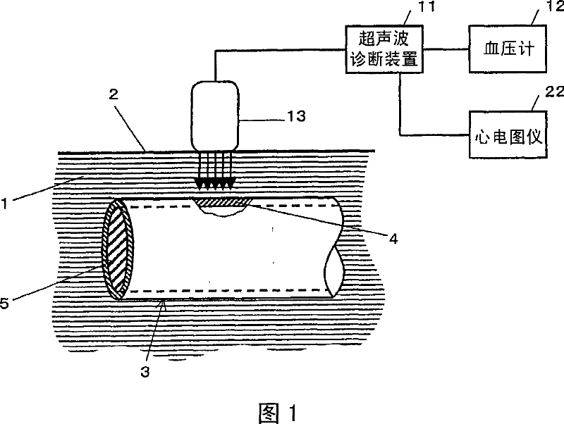
FIG. 1 is a block diagram showing a configuration when diagnosing properties of blood vessel wall tissue using an ultrasonic diagnostic apparatus 11 of the present invention. The ultrasonic probe 13 connected to the ultrasonic diagnostic apparatus 11 is placed in close contact with the body surface 2 of the subject, and sends ultrasonic waves into the extravascular tissue 1 . The transmitted ultrasonic waves are reflected and scattered by the blood vessel 3 and the blood 5 , and part of them returns to the ultrasonic probe 13 to be received as echoes (ultrasonic reflected waves). The ultrasonic diagnostic device 11 analyzes and calculates the received signal to obtain shape information and motion information of the anterior wall 4 of the blood vessel. Also, the sphygmomanometer 12 is connected to the ultrasonic diagnostic apparatus 11 , and blood pres...

no. 2 Embodiment approach

In this embodiment, an ultrasonic diagnostic apparatus and a control method thereof for displaying spatially distributed frames using the difference dn or the feature value Dn of the difference described in detail in the first embodiment will be described. The calculation method of the difference dn or the characteristic value Dn of the difference is the same as that described in the first embodiment. In addition, the configuration of the ultrasonic diagnostic apparatus not mentioned in particular below is the same as that of the first embodiment.

[0095]

FIG. 8 is a flowchart showing an example of controlling the ultrasonic diagnostic apparatus using the difference dn. A method of controlling the display of the spatial distribution frame is shown based on the comparison result of the difference dn obtained by the difference calculation unit 33 and the difference threshold ds set in advance by the operator of the ultrasonic diagnostic apparatus 11 . The steps described belo...

no. 3 Embodiment approach

In this embodiment, as in the second embodiment, an ultrasonic diagnostic apparatus and a control method for displaying spatially distributed frames using the difference dn or the difference feature value Dn described in detail in the first embodiment will be described. The calculation method of the difference dn or the characteristic value Dn of the difference is the same as that described in the first embodiment. In addition, the configuration of the ultrasonic diagnostic apparatus not mentioned in particular below is the same as that of the first embodiment.

[0108]

FIG. 10 is a flowchart showing an example of controlling the ultrasonic diagnostic apparatus using the difference dn. A method of controlling the display of the spatial distribution frame is shown based on the comparison result of the difference dn obtained by the difference calculation unit 33 and the difference threshold ds set in advance by the operator of the ultrasonic diagnostic apparatus 11 .

[0109] ...


PUM


Abstract

There is provided an ultrasonographic device including: a transmission unit (14) for driving an ultrasonic probe (13) for transmitting an ultrasonic transmission wave to a biological organ; a reception unit (15) for amplifying an ultrasonic reflected wave received reflected obtained by the ultrasonic transmission wave reflected by the biological organ and received by the ultrasonic probe (13) and generating a reception signal; a frame calculation unit (19) for calculating a spatial distribution frame indicating the spatial distribution of the shape measurement value or the state measurement value for each cardiac cycle of the biological body from the organ shape measurement value; a difference calculation unit (19) for calculating the difference of the shape measurement values or the state measurement values constituting the spatial distribution frame between the two spatial distribution frames selected from a plurality of spatial distribution frames obtained for each cardiac cycle; a storage unit for storing at least one of the shape measurement value, the state measurement value, and the difference; and a display unit (21) for displaying the spatial distribution frame.

Description

technical field [0001] The present invention relates to an ultrasonic diagnostic device, and more particularly to an ultrasonic diagnostic device for diagnosing properties of tissues in a living body and a control method for the ultrasonic diagnostic device. Background technique [0002] In recent years, the number of patients with blood circulation diseases such as myocardial infarction and cerebral infarction has been increasing, and the prevention and treatment of such diseases has become a major issue. [0003] The occurrence of myocardial infarction and cerebral infarction is closely related to arteriosclerosis. Specifically, when atherosclerosis is formed on the artery wall, or new cells of the artery cannot be formed due to various reasons such as high blood pressure, the artery loses its elasticity and becomes hard and brittle. Moreover, in the part where the atherosclerosis is formed, the blood vessel is blocked, or the vascular tissue covering the atheroscle...

Claims


Application Information

Patent Timeline
Patent Type & Authority Applications(China)
IPC IPC(8): A61B8/08
CPCG01S7/52036A61B5/021A61B8/543A61B8/08A61B8/485G01S15/899A61B5/02007G01S7/52087G01S7/52042
Inventor 加藤真萩原尚反中由直
Owner PANASONIC CORP
Why Eureka
Try Eureka