
Network device architecture for consolidating input/output and reducing latency

A technology of network equipment and network flow, applied in the direction of network interconnection, transmission system, data exchange through path configuration, etc.

Active Publication Date: 2007-09-19
CISCO TECH INC
View PDF2 Cites 4 Cited by
  • Summary
  • Abstract
  • Description
  • Claims
  • Application Information

AI Technical Summary

Problems solved by technology

So the Infiniband based cost will not be a replacement cost but an additional cost

Method used


Image

  • Network device architecture for consolidating input/output and reducing latency
  • Network device architecture for consolidating input/output and reducing latency
  • Network device architecture for consolidating input/output and reducing latency

Examples


Embodiment Construction

[0056] Reference will now be made in detail to specific embodiments of the invention, including what the inventors believe are the best modes of carrying out the invention. Examples of these specific embodiments are illustrated in the accompanying drawings. While the invention is described in conjunction with these specific embodiments, it will be understood that it is not intended to limit the invention to the described embodiments. On the contrary, it is intended to cover alternatives, modifications and equivalents as included within the spirit and scope of the invention as defined by the appended claims. Furthermore, numerous specific details are set forth below in order to provide a thorough understanding of the present invention. The invention may be practiced without these specific details. In other instances, well-known process operations have not been described in detail so as not to obscure the topic.

[0057] The present invention provides methods and apparatus fo...


PUM


Abstract

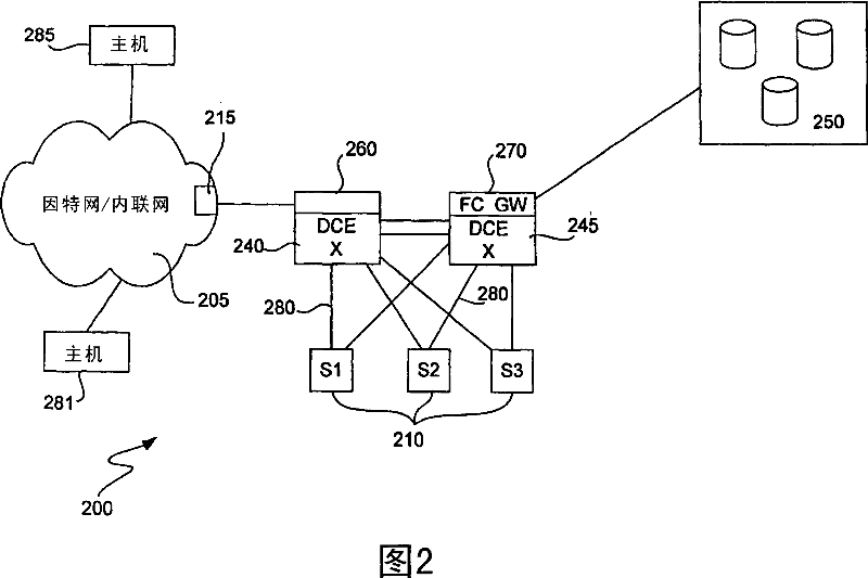
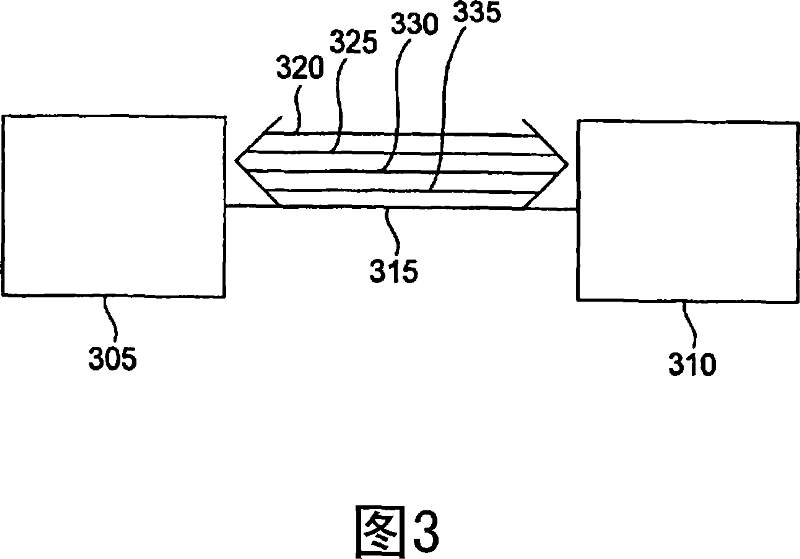
The present invention provides methods and devices for implementing a Low Latency Ethernet (''LLE'') solution, also referred to herein as a Data Center Ethernet (''DCE'') solution, which simplifies the connectivity of data centers and provides a high bandwidth, low latency network for carrying Ethernet and storage traffic. Some aspects of the invention involve transforming FC frames into a formatsuitable for transport on an Ethernet. Some preferred implementations of the invention implement multiple virtual lanes (''VLs'') in a single physical connection of a data center or similar network. Some VLs are ''drop'' VLs, with Ethernet-like behavior, and others are ''no-drop'' lanes with FC-like behavior. Some preferred implementations of the invention provide guaranteed bandwidth based on credits and VL. Active buffer management allows for both high reliability and low latency while using small frame buffers. Preferably, the rules for active buffer management are different for drop and no drop VLs.

Description

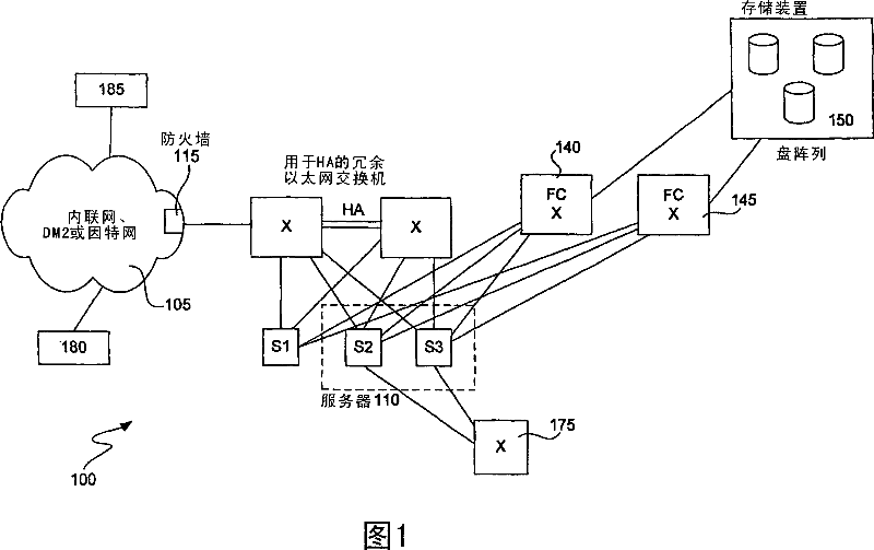
[0001] Cross References to Related Applications [0002] This application is based upon U.S. Provisional Application No. 60 / 621,396 (Attorney Docket No. CISCP404P), filed October 22, 2004, entitled "FC Over Ethernet" and filed March 30, 2005, entitled "Network Device Architecture For Consolidating Input / Output And Reducing Latency," U.S. Patent Application No. 11 / 094,877 (Attorney Docket No. CISCP 417), which are hereby incorporated by reference in their entirety. Background technique [0003] Figure 1 shows a simplified version of a general type of data center that might be used by a business requiring high availability and networked storage, such as a financial institution. Data center 100 includes redundant Ethernet switches with redundant connections for high availability. Data center 100 is connected to clients via network 105 via firewall 115 . Network 105 may be, for example, a corporate intranet, a DMZ, and / or the Internet. Ethernet is well suited for TCP / IP traffic...

Claims


Application Information

Patent Timeline
IPC IPC(8): H04L12/28H04L12/46H04L29/06
Inventor 西尔瓦诺·加伊托马斯·埃兹尔戴维·贝尔加马斯科迪内希·达特弗拉维欧·博诺米
Owner CISCO TECH INC
Learn More