
Light pedestrian bridge suspended below flyover

A technology for pedestrian bridges and overpasses, applied in bridges, open bridges, bridge applications, etc., can solve the problems of affecting project scale, poor landscape effect, and many lower components, so as to reduce self-weight, steel consumption, and control The effect of point elevation and good permeability

Active Publication Date: 2007-09-26
POWERCHINA HUADONG ENG COPORATION LTD
View PDF0 Cites 3 Cited by
  • Summary
  • Abstract
  • Description
  • Claims
  • Application Information

AI Technical Summary

Problems solved by technology

[0007] With the modernization of the city, the flyover at the intersection of urban roads often needs to consider the advanced facilities for pedestrians to cross at the same time. In addition to the limitations of conventional structures such as high cost, many substructures, large structural thickness when the span is large, and poor landscape effects, the control point elevation of the entire flyover bridge will be raised due to the increase in the structural height of the pedestrian bridge, which will affect the entire project scale.
In addition, the substructure of the pedestrian bridge will restrict ground traffic, and it will also cause conflicts between the foundation and pipelines in places where underground pipelines are dense

Method used


Image

  • Light pedestrian bridge suspended below flyover
  • Light pedestrian bridge suspended below flyover
  • Light pedestrian bridge suspended below flyover

Examples


Embodiment 1

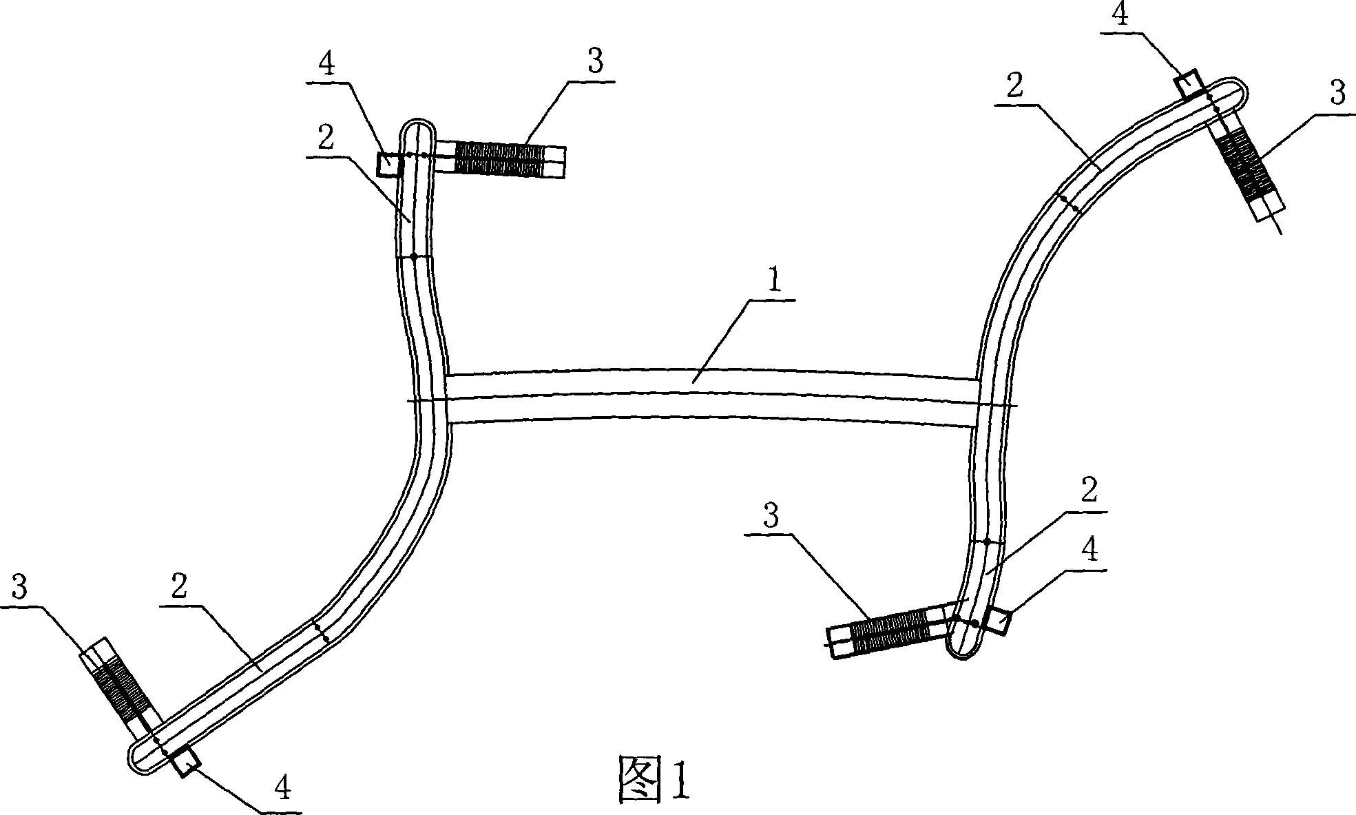
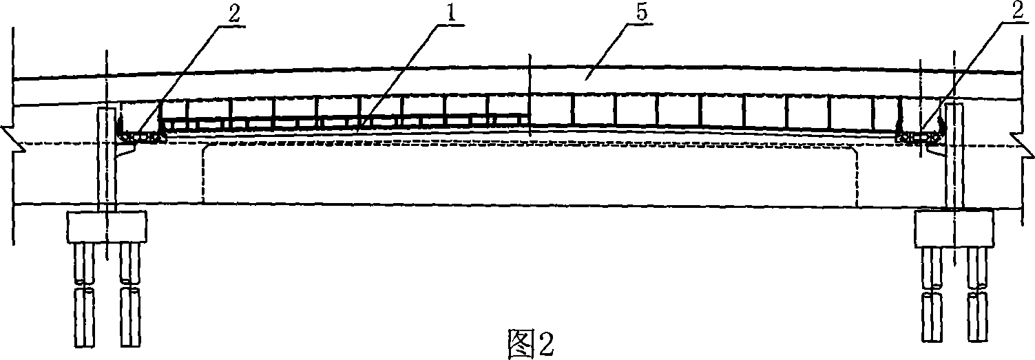
[0024] Embodiment 1, the present embodiment is a light-duty pedestrian bridge suspended under the urban overpass by rigid vertical suspenders 1-3 and parallel to the overpass. The bridge span of the main bridge of the crossover bridge in this example is 3×30m+(50+70+50)m+3×30m=350m (that is, the first and third couplets are provided with a pier every 30m, and the second couplet is in The two ends of the 70m span and the ends of the two 50m spans are provided with piers), the first and third superstructures are prestressed concrete continuous box girders with equal cross-sections, and the second superstructure is continuous steel box girders with equal cross-sections, in order to ensure the beautiful appearance of the bridge And the continuity of the lines, all the joints use 2m beam height. In order not to affect the sight distance of vehicles entering and exiting the intersection, the main bridge does not set up piers in the intersection, and uses a 70m span to span directly....

Embodiment 2

[0027] Embodiment 2, the basic structure of this embodiment is the same as that of Embodiment 1, the difference is only that the vertical suspender 1-3 adopts a flexible suspender, such as: thick steel bar (fine-rolled rebar), parallel steel wire The connection between the flexible vertical suspender and the steel box girder diaphragm 5 of the flyover bridge is anchorage, and the connection with the double main longitudinal girder 1-1 can also be anchorage. In order to increase the lateral stability of the overpass, an oblique suspender 1-9 is arranged between the steel box girder diaphragm 5 and the main longitudinal girder 1-1 of the flyover bridge, and the oblique suspender is connected to the steel box girder diaphragm 5 above and Same as Example 1, the one-way hinge structure is adopted (the connection with the diaphragm can be transitioned to be perpendicular to the plate), that is, it can rotate freely in the horizontal direction, and the inclined suspender can be welded...


PUM


Abstract

The invention relates to a light walkway flying gangway, suspended under flyover, which is not existed in present nation, to make the flying gangway light, reduce cost, and obtain beautiful view without affecting the whole project of flyover, ground traffic and underground tube. The invention comprises a light walkway flying gangway, characterized in that it includes a walkway flying gangway suspended under the flyover via lifting rod and parallel with the flyover, while the main bridge comprises a bridge plate, two main longitudinal beams, beams uniformly arranged between the main longitudinal beams, and bars at two sides of the bridge plate, wherein two ends of the main bridge are arranged with guiding bridges. People can use the invention to cross street.

Description

technical field [0001] The invention relates to a conventional urban pedestrian overpass, in particular to a light pedestrian overpass suspended under the overpass provided across the urban overpass. It is suitable for pedestrian crossing in urban blocks. Background technique [0002] In the prior art, common overpasses can be divided into three categories according to their structures, namely suspended structures, supporting structures and hybrid structures. [0003] (1) Hanging structure. The overpass with a suspended structure uses the bridge railing as the main load-bearing component, and the bridge deck for pedestrians to pass is suspended on the bridge railing as a load-bearing beam, and the bridge deck itself is not load-bearing. The overpass of this structure combines structural components and practical components, which can reduce the use of building materials and reduce the cost of the project. However, the railings of the overpass bridge with this structure are ...

Claims


Application Information

Patent Timeline
IPC IPC(8): E01D18/00E01D15/08
Inventor 韦华李小刚蒋鹰冲郭文复王紫娟郭忠陈阶亮郑斐潘杰
Owner POWERCHINA HUADONG ENG COPORATION LTD
Learn More