Optical ranging sensor and warm water wash toilet seat
A distance measuring sensor, optical technology, applied in the direction of measuring distance, using optical devices, instruments, etc., can solve the problem of uncertain distance measurement accuracy between the near side and the far side, and achieve a simple structure and uniform ranging accuracy Effect
- Summary
- Abstract
- Description
- Claims
- Application Information
AI Technical Summary
Problems solved by technology
Method used
Image

Examples
no. 1 Embodiment
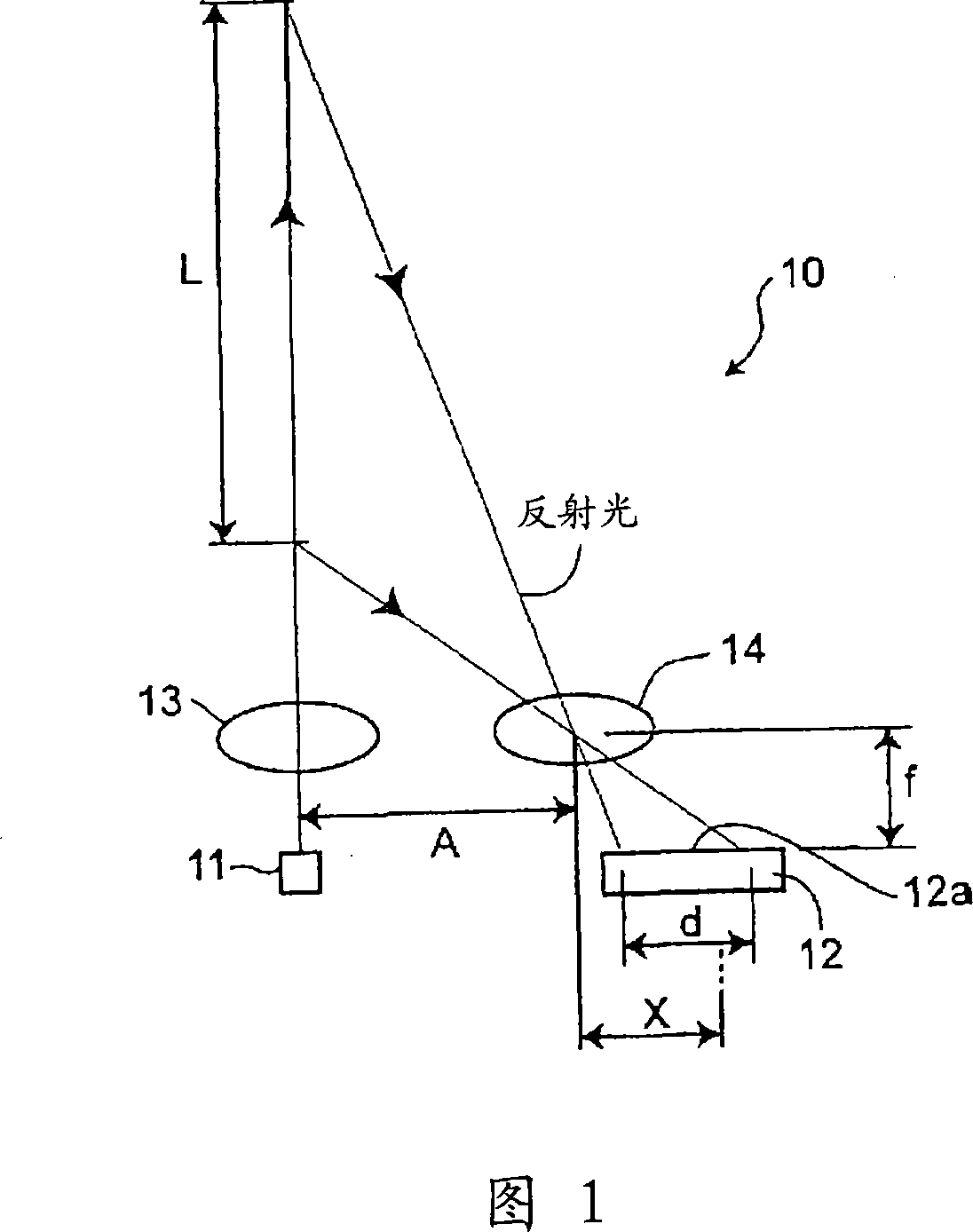
[0106] FIG. 1 is a schematic diagram showing the basic structure of an optical distance measuring sensor according to a first embodiment of the present invention.
[0107] The optical distance measuring sensor 10 of the first embodiment includes, as shown in FIG. 1 , a light emitting element 11 that emits light; distance object; light-sensing light-sensing mechanism 14, which condenses the reflected light from the above-mentioned distance-measuring object (not shown); photosensitive element 12, which is arranged so that the photosensitive surface is perpendicular to the optical axis of the light emitted from the above-mentioned light-emitting element 11 , to receive the reflected light condensed by the photosensitive light condensing mechanism 14 .
[0108] The light-emitting element 11 is a light source such as a light-emitting diode, and the light emitted from the light-emitting element 11 is collected by the light-projecting light-concentrating mechanism 13 provided on the ...
no. 2 Embodiment
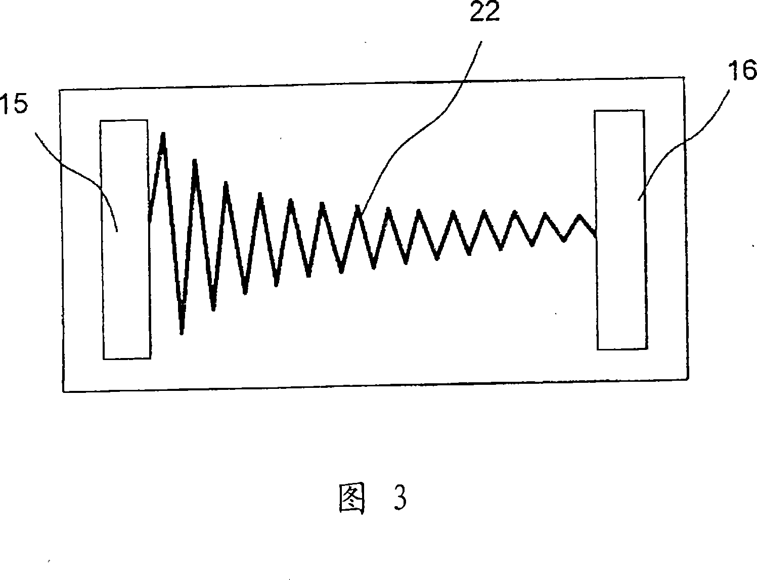
[0139] 3 is a diagram showing a photosensitive surface of a PSD used as a photosensitive element of an optical distance measuring sensor according to a second embodiment of the present invention. In addition, the optical distance measuring sensor of the second embodiment has the same structure as that of the optical distance measuring sensor of the first embodiment except for the PSD, and FIG. 1 is referred to, and description thereof is omitted.
[0140] As shown in FIG. 3 , in the PSD of the optical distance measuring sensor according to the second embodiment, a zigzag-shaped resistance region 22 is formed in the p-layer. This resistance region 22 is designed such that: the line width of the broken line and the turn-back distance are constant, the amplitude length is changed, the resistance value between the first and the second electrodes 15, 16 and the distance from the optical axis of the light-sensing light-collecting mechanism 14 Inversely proportional.
[0141] As the...
no. 3 Embodiment
[0143]FIG. 4 shows a photosensitive surface of a PSD used as a photosensitive element of an optical distance measuring sensor according to a third embodiment of the present invention. In addition, the optical distance measuring sensor of the third embodiment has the same structure as that of the optical distance measuring sensor of the first embodiment except for the PSD, and its description is omitted with reference to FIG. 1 .
[0144] As shown in FIG. 4 , in the optical distance measuring sensor PSD of the third embodiment, a zigzag-shaped zigzag-shaped resistive region 23 is formed from the p- layer. This resistance region 23 is set so that: the line width of the folded line, the amplitude length is constant, the turn-back pitch is changed, the resistance value between the first and the second electrodes 15, 16 and the distance from the optical axis of the light-sensing light-collecting mechanism 14 The distance is inversely proportional.
[0145] In the PSD of the above ...
PUM
 Abstract
Description
Claims
Application Information
 - R&D
- Intellectual Property
- Life Sciences
- Materials
- Tech Scout
- Unparalleled Data Quality
- Higher Quality Content
- 60% Fewer Hallucinations
Browse by: Latest US Patents, China's latest patents, Technical Efficacy Thesaurus, Application Domain, Technology Topic, Popular Technical Reports.
© 2025 PatSnap. All rights reserved.Legal|Privacy policy|Modern Slavery Act Transparency Statement|Sitemap|About US| Contact US: help@patsnap.com