Detecting method for position of photomask graphics

A detection method and photomask technology, which are applied to the photoengraving process of the pattern surface, the originals for photomechanical processing, the exposure device of the photoengraving process, etc., can solve the problem of high risk of time-consuming and undetected, Achieve the effect of improving detection efficiency and detection accuracy, saving economic costs and reducing detection costs

Inactive Publication Date: 2007-09-26
SEMICON MFG INT (SHANGHAI) CORP +1
View PDF1 Cites 2 Cited by
  • Summary
  • Abstract
  • Description
  • Claims
  • Application Information

AI Technical Summary

Problems solved by technology

[0008] In order to solve the shortcomings of the time-consuming manual inspection method in the prior art and the high risk of undetected defects, the present invention provides a fast and efficient detection method for the position

Method used


Image

  • Detecting method for position of photomask graphics
  • Detecting method for position of photomask graphics
  • Detecting method for position of photomask graphics

Examples


Example Embodiment

[0035] In order to better illustrate the present invention, the following further describes the present invention with reference to the accompanying drawings and embodiments.

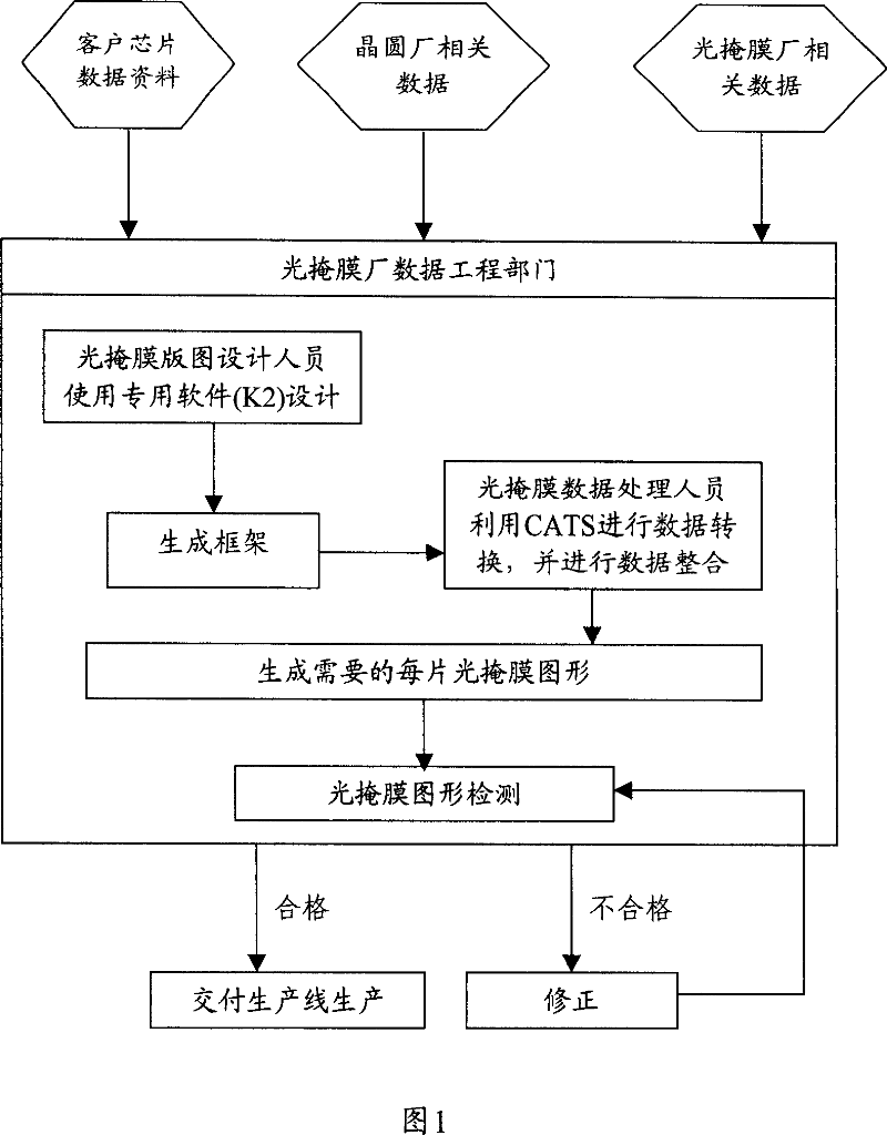
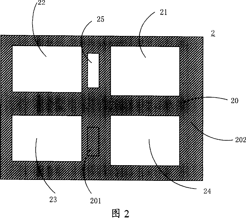
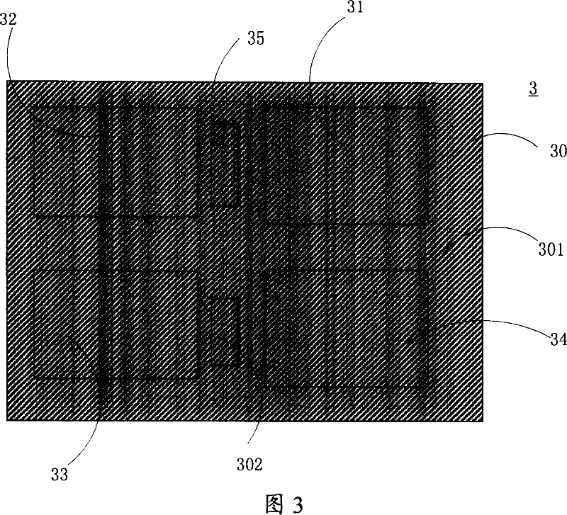
[0036] The invention makes full use of computer software and hardware resources and the photomask layout and photomask frame generated in the computer to process graphics and data through the computer to achieve the purpose of computer automatic detection, so as to improve detection efficiency and detection accuracy. The position detection of the photomask pattern of the present invention is mainly divided into the following two parts: the first part is to detect whether there is an overlap between the frame pattern and the filling pattern on the photomask layout; the second part is to detect the photomask layout Whether there are overlaps or gaps between the filled graphics and the filled graphics.

[0037] In the first part of the photomask pattern position detection, since the frame pattern of the photom...


PUM


Abstract

This invention relates to one light mask pattern position test method, which comprises the following steps: totalizing mask film edit pattern each filling area as reference area; forming fill-in pattern module graph by each fill graph position and drawing software in the pattern; computing fill-in pattern module area in the graph process software and comparing the reference total area with the filled area; if not, then correcting the light mask pattern design and repeating above steps; if yes, then closing the test.

Description

technical field [0001] The invention relates to the field of semiconductor manufacturing, in particular to a method for detecting the position of a photomask pattern. Background technique [0002] When forming a circuit pattern of a semiconductor device, a photosensitive material such as a photoresist is coated on a working film on a semiconductor substrate, and then the photosensitive material is exposed and developed by a reduced projection photolithography machine. When using a photolithography machine with a refractive optical system, the light emitted from the light source passes through the illumination optical system and the projection optical system, and the circuit pattern of the photomask located between the two optical systems is reduced and projected onto the photoresist film . A photoresist pattern having a circuit pattern transferred thereon by development is formed on the working film. Using the photoresist pattern as a mask, the working film is processed by...

Claims


Application Information

Patent Timeline
IPC IPC(8): G03F7/20G03F1/00H01L21/027G03F1/44
Inventor 李峥胡振宇
Owner SEMICON MFG INT (SHANGHAI) CORP
Why Eureka
Try Eureka