Wireless receiving and dispatching system

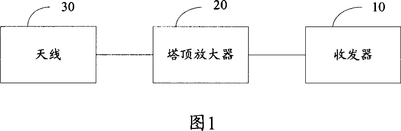
A wireless transceiver system and transceiver technology, applied in the field of communication systems, can solve the problems of transmission loss, the output power of the tower top amplifier 20 exceeds the legal power, the tower top amplifier 20 cannot work, etc., and achieves the effect of improving efficiency

Inactive Publication Date: 2007-09-26
HONG FU JIN PRECISION IND (SHENZHEN) CO LTD +1
View PDF0 Cites 8 Cited by
  • Summary
  • Abstract
  • Description
  • Claims
  • Application Information

AI Technical Summary

Problems solved by technology

Therefore, there is a transmission loss between the transceiver 10 and the tower mount amplifier 20, which includes cable loss (Cable Loss) and connection loss (Connector Loss)
[0003] Since the transmission loss between the transceiver 10 and the tower mounted amplifier 20 cannot be accurately measured before the installation of the wireless transceiver sy

Method used


Image

  • Wireless receiving and dispatching system
  • Wireless receiving and dispatching system
  • Wireless receiving and dispatching system

Examples


Embodiment Construction

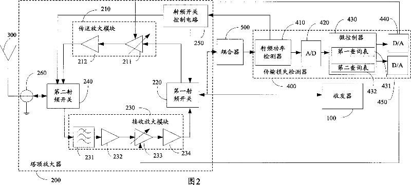
[0010] Referring to FIG. 2 , it is a block diagram of an embodiment of the wireless transceiving system (Wireless Transceiving System) of the present invention. In this embodiment, the wireless transceiver system is in Time Division Duplex (TimeDivision Duplex) mode. The wireless transceiver system can accurately compensate transmission loss, which includes a transceiver (Transceiver) 100 , a tower mounted amplifier (Tower Mounted Amplifier, TMA) 200 , an antenna (Antenna) 300 and a transmission loss detector (Transport Loss Detector) 400 . The antenna 300 and the tower mounted amplifier 200 are located outdoors, and the tower mounted amplifier 200 is connected to the antenna 300, and the transceiver 100 is located indoors. The indoor transceiver 100 is connected to the outdoor tower mount amplifier 200 through a cable, so there is a transmission loss between the transceiver 100 and the tower mount amplifier 200 . In this embodiment, the transmission loss includes cable loss ...


PUM


Abstract

A wireless receiving and sending system is used to compensate the loss of transmission, it includes antenna, transceiver, tower top amplifier and transmission loss detector. The transceiver is used to send power and the first signal. The tower top amplifier is connected with the cable to receive the second signal from the transceiver, and zoom the second signal; the second signal is the first signal which passes the attenuation of cable. The transmission loss detector is connected between the tower top amplifier and the transceiver to detect that whether the transceiver remit signal, calculating the loss between the transceiver and the tower top amplifier. The tower top amplifier is used to remit signal to antenna or receive signal from antenna based on the detect result of the transmission loss detector, and compensates said transmission loss. Said wireless receiving and sending system can compensate transmission loss between the transceiver and tower top amplifier precisely.

Description

【Technical field】 [0001] The invention relates to a communication system, in particular to a wireless transceiver system. 【Background technique】 [0002] Referring to FIG. 1 , it is a schematic diagram of a traditional wireless transceiver system. A traditional wireless transceiver system includes a transceiver 10 , a Tower Mounted Amplifier (Tower Mounted Amplifier, TMA) 20 and an antenna 30 . The antenna 30 and the tower mounted amplifier 20 are located outdoors, and the tower mounted amplifier 20 is connected to the antenna 30, and the transceiver 10 is located indoors. The indoor transceiver 10 is connected to the outdoor tower mount amplifier 20 through a cable. Therefore, there is a transmission loss between the transceiver 10 and the tower mount amplifier 20 , which includes cable loss (Cable Loss) and connection loss (Connector Loss). [0003] Since the transmission loss between the transceiver 10 and the tower mounted amplifier 20 cannot be accurately measured be...

Claims


Application Information

Patent Timeline
IPC IPC(8): H04B1/40H04B1/38H04B7/26
Inventor 翁国执邱木荣别正宜
Owner HONG FU JIN PRECISION IND (SHENZHEN) CO LTD
Why Eureka
Try Eureka