
Thin film forming apparatus and method thereof

A film and substrate technology, applied in the field of forming electrode films of piezoelectric elements, can solve the problems of shortened maintenance cycle, idle rollers, and many bolts, etc., and achieve the effect of improving utilization rate and improving handling parts.

Inactive Publication Date: 2010-05-12
SHOWA SHINKUKK
View PDF1 Cites 0 Cited by
  • Summary
  • Abstract
  • Description
  • Claims
  • Application Information

AI Technical Summary

Problems solved by technology

If only the utilization rate of the target material is considered, it is ideal that the cathode power supply is always turned on, and the substrate is continuously supplied to the continuously maintained film formation area. The tank size is not practical
In addition, when the vacuum chamber is of a normal size, it is necessary to sequentially transport the substrates from the atmosphere into the limited vacuum space, and transport the processed substrates out of the atmosphere again, so it is inevitable to release the target material in vain. indoor
When the target material is released in vain, the utilization rate of the target material is reduced, the maintenance cycle of the device is shortened, and expensive metal materials such as Au or Ag, which are often used as good conductive materials for the electrode film of the crystal vibrator, are wasted, which also causes costs. greater impact
[0011] In addition, due to the deviation of the height of the roller within the mechanical tolerance of the existing conveying device, there is a possibility that the roller will idle during the conveyance
Although the both sides of the base plate are in contact with the bearings and move straight, if there is a deviation in the position of the bearings, etc., the base plate and the bearings collide, and the roller may idle due to the above impact.
Film formation is controlled by the conveying speed and conveying position of the substrate tray, but when the rollers run idle, the conveying speed and conveying position cannot be controlled, the desired film thickness cannot be obtained, and the yield decreases
[0012] Furthermore, since it is a mechanism that drives a plurality of motors synchronously by installing a drive motor for the transport roller in each chamber, the components are complicated and difficult to adjust.
[0013] Furthermore, the existing cathodes are fixed by bolts, so the number of bolts is large, the installation is time-consuming and labor-intensive, and the maintenance is also time-consuming

Method used


Image

  • Thin film forming apparatus and method thereof
  • Thin film forming apparatus and method thereof
  • Thin film forming apparatus and method thereof

Examples


Embodiment Construction

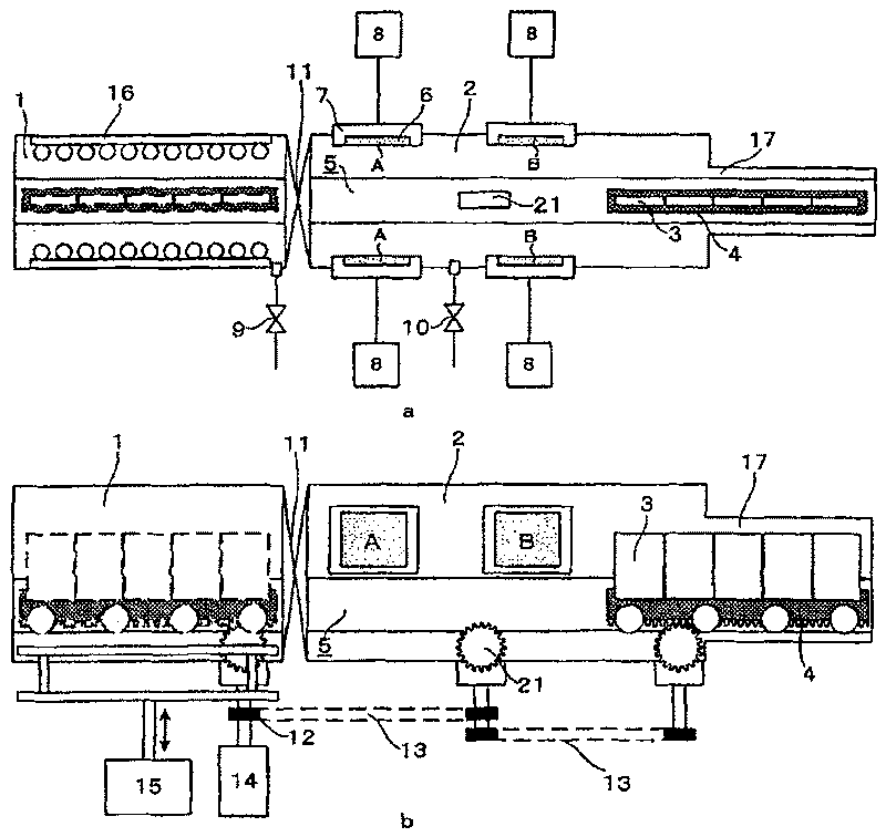
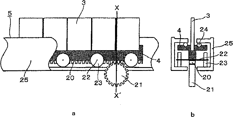
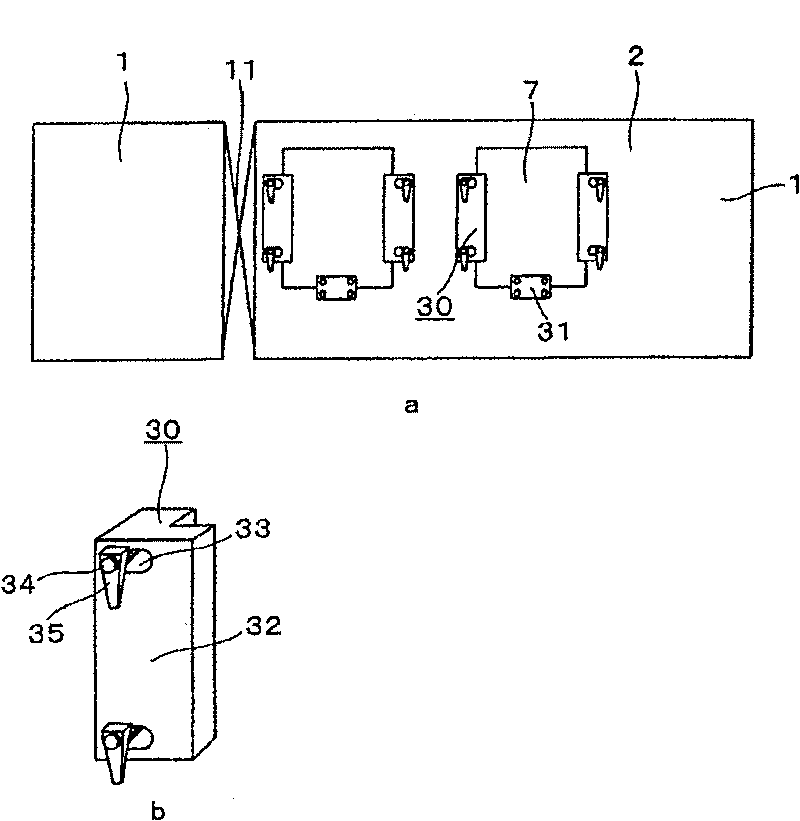
[0071] figure 1 An example of the electrode film forming apparatus of the present invention is shown, and the same parts as those in the prior art are given the same reference numerals and their descriptions are omitted. The device consists of a preparation and removal chamber 1 and a film formation chamber 2, figure 1 a is a schematic view of the interior of each chamber viewed from above. figure 1 b is a schematic view of the interior of each chamber viewed from the side. The embodiment omits the stocker for the purpose of improving productivity and reducing the area occupied by the device, and the stocker can also be provided as required.

[0072] The preparation taking out chamber 1 and the film forming chamber 2 are separated by a gate valve 11 , the film forming chamber 2 is connected with a main valve 10 , and the preparation taking out chamber 1 is connected with a roughing valve 9 . The main valve 10 is connected to the main pump not shown, and the roughing valv...


PUM


Abstract

A utilization ratio of a target material, a tact time, maintenance easiness and film forming accuracy are improved by a thin film forming apparatus. The thin film forming apparatus is provided with avacuum chamber, a sputter cathode for holding the target material, a placing means for placing a substrate to be deposited with the sputtered target material and a carrying mechanism for the placing means. In the carrying mechanism, a carrying path is provided so as to permit the substrate pass through the front side of the target material, and the placing means is composed of a substrate tray which can hold a plurality of substrates in juncture.

Description

technical field [0001] The invention relates to a thin film forming device and a thin film forming method, in particular to electrode films for forming piezoelectric elements. Background technique [0002] The resonant frequency of a crystal vibrator, which is a typical piezoelectric element, is determined by the thickness of a crystal plate as a rough-processed plate and the film thickness of a metal electrode formed on the surface thereof. In order to obtain a crystal resonator with a desired frequency, first, a crystal wafer is cut out to a predetermined thickness, the surface is ground, and a metal electrode film is formed on the surface by sputtering or the like. In order to increase productivity, it is necessary to process multiple crystal wafers continuously. Therefore, the following method is generally used: mount multiple crystal wafers on a substrate tray or a moving body called a carrier, and supply them sequentially to The electrode film is formed in a film-form...

Claims


Application Information

Patent Timeline
Patent Type & Authority Patents(China)
IPC IPC(8): C23C14/34H01L41/09H01L41/18H01L41/22H03H3/02H01L41/29
CPCC23C14/566H03H3/02C23C14/50C23C14/3407C23C14/568H01J37/32743H01J37/32779H01J37/34
Inventor 藤原隆行永井和芳
Owner SHOWA SHINKUKK
Learn More