Exhaust system and method for joining components of an exhaust system

A technology of exhaust system and connection method, which is applied to exhaust devices, welding equipment, engine components, etc., and can solve problems such as unfavorable strength and impact

Inactive Publication Date: 2007-09-26
ARVINMERITOR EMISSIONS TECH GMBH
View PDF0 Cites 13 Cited by
  • Summary
  • Abstract
  • Description
  • Claims
  • Application Information

AI Technical Summary

Problems solved by technology

In addition, welds have a...

Method used


Image

  • Exhaust system and method for joining components of an exhaust system
  • Exhaust system and method for joining components of an exhaust system
  • Exhaust system and method for joining components of an exhaust system

Examples


Embodiment Construction

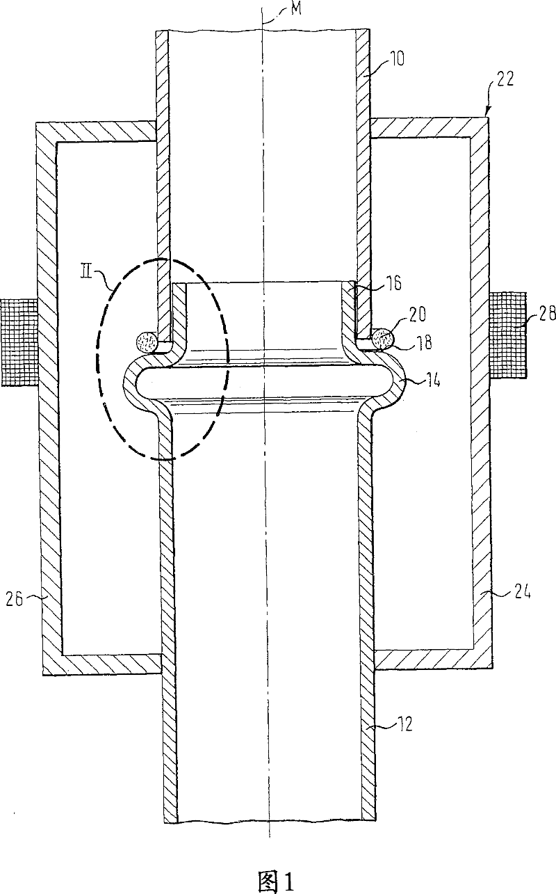
[0025] FIG. 1 shows two components 10 and 12 , in the present embodiment two ducts for an exhaust system of a motor vehicle. Here, it should be noted that basically components other than pipes can also be connected to each other, such as a funnel with a pipe, a funnel with a casing, and the like.

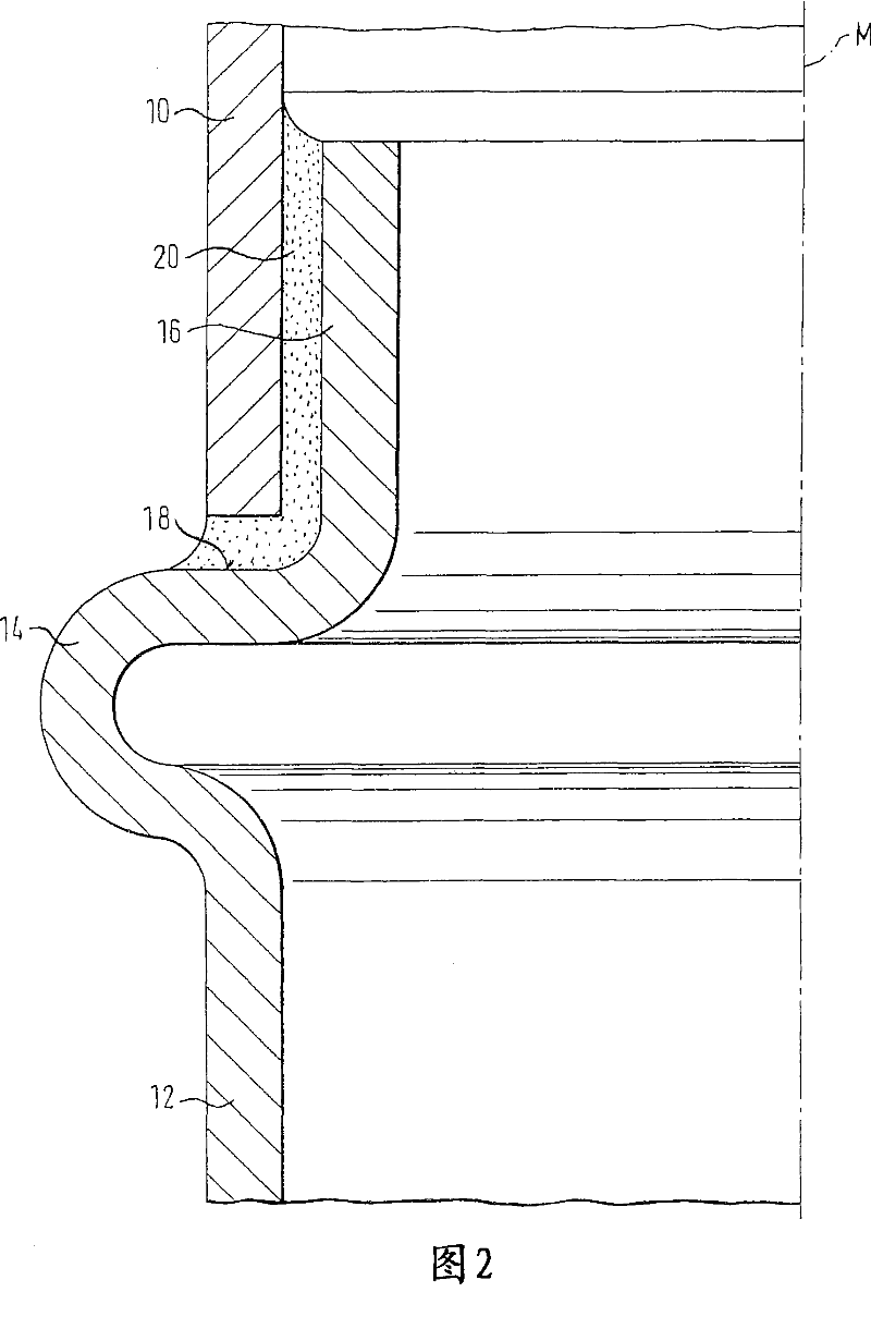
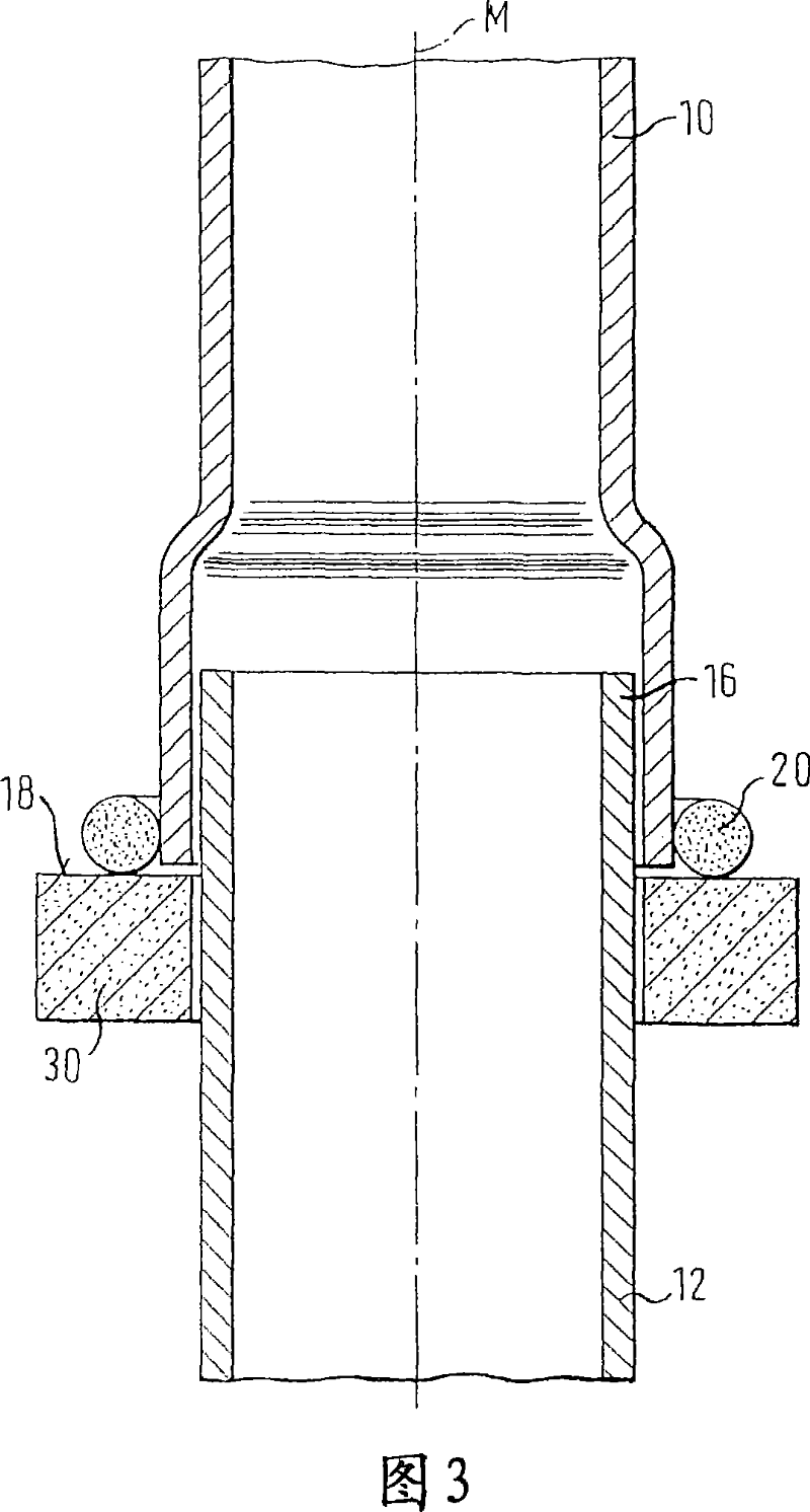
[0026] The first part 10 has a constant cross-section, while the end of the second part 12 facing the first part 10 has an outwardly facing bead 14 and an insertion portion 16 close to the bead 14 . The outer diameter of the insert part 16 is slightly smaller than the inner diameter of the first part 10 .

[0027] The region of the weld bead 14 facing the component 10 and arranged perpendicular to the middle axis M forms a support surface 18 on which the annular solder 20 rests. In this way, the solder is located in the region of the solder joint formed between the insert part 16 of the second component 12 and the first component 10 . The solder 20 is a copper-based or nickel-base...


PUM


Abstract

An exhaust system comprising a first component and a second component is characterized in that an induction soldered joint is provided between these two components (10, 12). According to a method for joining a first component of a motor vehicle exhaust system with a second component, the invention provides that two components, which are fitted together and provided with a high-temperature soldering material (20) are heated in the area of the soldering material by means of an inductor (28) to a temperature higher than the melting point of the soldering material (20).

Description

technical field [0001] The invention relates to an exhaust system, in particular to an exhaust system for a motor vehicle, and also to a method for connecting two components of an exhaust system, in particular for a motor vehicle. Background technique [0002] The components to be interconnected are in particular the ducts of the exhaust system which lead the exhaust gas from the output manifold to eg a catalytic converter or a muffler. Due to the high temperatures and high dynamic stresses to which exhaust system components are exposed, until now these components have always been joined by welded seams. In fact, there are some drawbacks if the components of the exhaust system are welded to each other. One of the disadvantages is that, for example, a considerable footprint is required for automatic welding machines or welding robots in order to carry out the method. In both cases, the parts to be welded together must be moved relative to the horn. Therefore, complex means...

Claims


Application Information

Patent Timeline
IPC IPC(8): F01N7/18B23K1/002F01N13/18
CPCF01N13/1838F01N2450/22F01N13/18F01N13/00
Inventor 艾尔弗雷德·布吕姆崔洪江
Owner ARVINMERITOR EMISSIONS TECH GMBH
Why Eureka
Try Eureka