
Method of manufacturing injection needle and injection needle

A manufacturing method and technology of injection needles, which are applied in the manufacture of injection needles and the field of injection needles, can solve the problems of poor liquid flow, cumbersome manufacturing process, increased manufacturing time and cost, and achieve the effect of simplifying the manufacturing process and ensuring smooth flow

Inactive Publication Date: 2007-10-03
日本插芯株式会社
View PDF1 Cites 6 Cited by
  • Summary
  • Abstract
  • Description
  • Claims
  • Application Information

AI Technical Summary

Problems solved by technology

[0004] But above-mentioned prior art all is the method from rolling the flat stainless steel material into a circle to make a cylinder, to the mutual welding of the end faces of the roll circle butt joints, etc., so all need the processing of joining, no matter what will happen. Creates poor flow of fluid at the seams of this joint
In addition, due to the addition of complicated processes such as rolling and joining of flat stainless steel, the time and cost of manufacturing will increase.
[0005] In addition, as a manufacturing technique for metal thin-diameter pipes such as stainless steel materials, a method of drawing a large-diameter metal steel pipe to make the diameter smaller is also known. However, after such a drawing process is performed on the metal steel pipe, The inner wall will have fine wrinkles, and if the inner wall is not ground, it will be difficult to ensure the smooth flow of liquid, so it will be difficult to use this method to manufacture injection needles in practice
Moreover, when carrying out such stretching processing, machine oil must be used in the manufacturing process, and when it is applied to injection needles, it must be fully degreased, which makes the manufacturing process more cumbersome

Method used


Image

  • Method of manufacturing injection needle and injection needle
  • Method of manufacturing injection needle and injection needle
  • Method of manufacturing injection needle and injection needle

Examples


Embodiment Construction

[0034] The present invention will be further described below in conjunction with the accompanying drawings and typical embodiments.

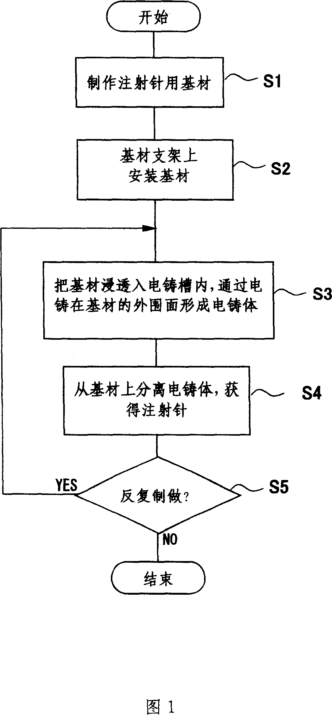
[0035] Fig. 1 shows a flowchart of the manufacturing process of the injection needle manufacturing method.

[0036] First, a base material for injection needles is produced (S1).

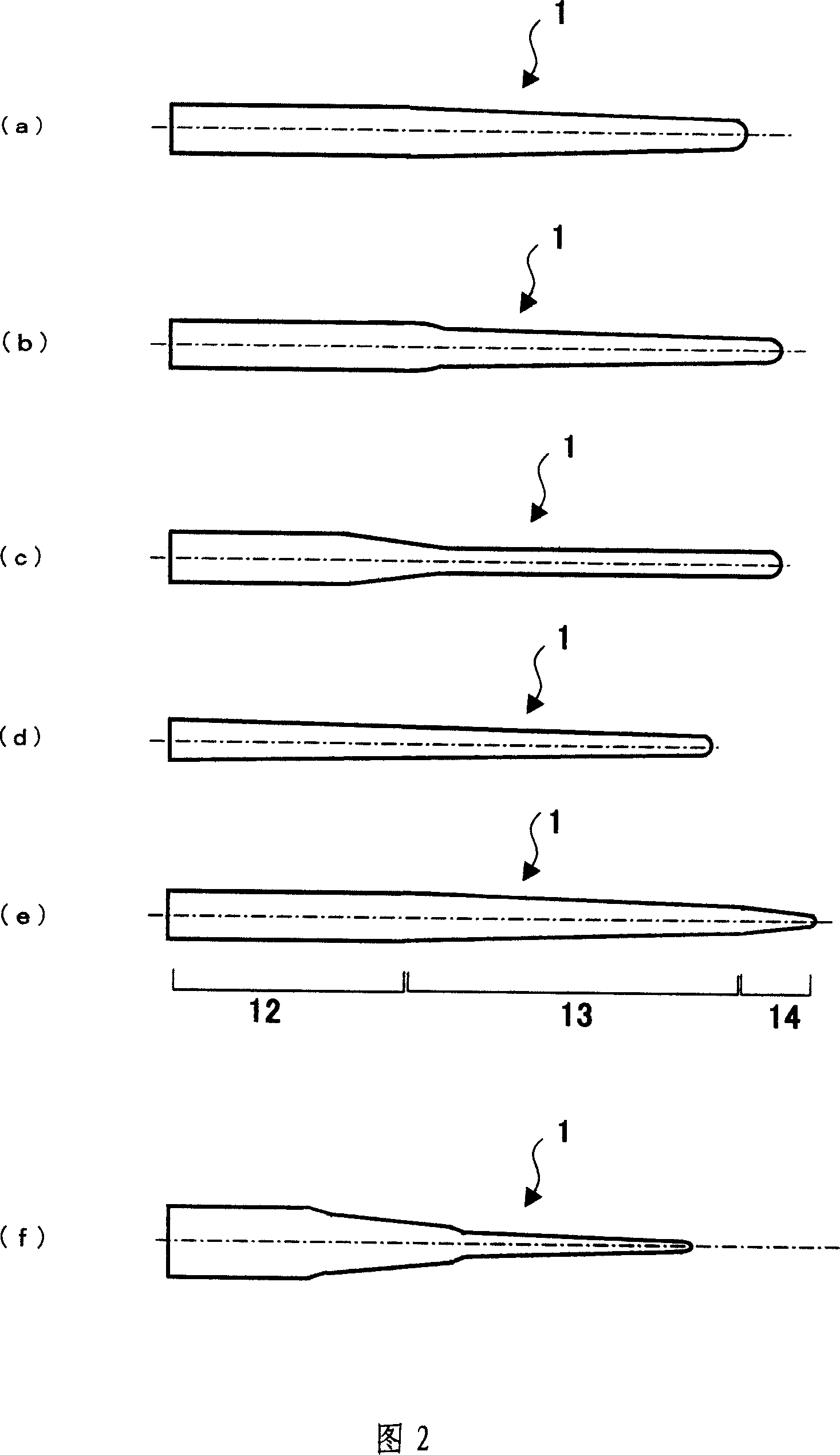
[0037] The manufacturing process of this base material is to manufacture the base material 1 for injection needles used as a molding die for the shape of the inner wall of the injection needle. The material is conductive material such as stainless steel (SUS) or non-conductive material (materials such as conductively treated plastic and nylon), and the outer surface is polished to a mirror finish. The base material 1 for injection needles in which at least a part of the outer part has a tapered shape is shown in Fig. 2 (a) to (e). Of course, it is by no means limited to this example, and it is also possible to have a rod-shaped shape without any taper. . Moreover, ...


PUM


Abstract

The invention relates to the manufacture of injection needle, which is aimed to simply obtain an injection needle which dispenses with jointing treatment when a cylindrical shape with a small diameter is made, and enables the smooth flow of a liquid to be ensured without polishing treatment of an inner wall surface. Firstly, a master for the injection needle is made (S1); secondly, a master retaining holder is fitted with the master for the injection needle (S2); subsequently, an electroformed metal adheres to the master for the injection needle by electroforming treatment (S3); and finally, the master for the injection needle is pulled up from an electroforming tank along with the master retaining holder, so that an electroformed body as an injection needle body can be released from the master for the injection needle (S4). In the manufactured injection needle, an outside diameter of a leading end for a puncture is set on the order of 0.12 mm; and a tapered part, the outside and inside diameters of which are reduced toward the leading end, is arranged between a proximal end part and the distal end part for the puncture. The invention simplifies the manufacture of injection needle, and enables the smooth flow of a liquid in the injection needle, further, greatly reduces the pain in puncture.

Description

technical field [0001] The present invention relates to a method of manufacturing injection needles used for injecting liquids such as medicinal liquid into the body, and products related to injection needles manufactured thereby, and particularly relates to ultra-fine injection needles with a tip diameter of about 0.25 mm or less, for example. Methods of manufacture and articles related to injectable needles. Background technique [0002] Generally, when the outer diameter of the injection needle is about 0.3mm to 2.0mm, it is relatively thin. The injection needles used for insulin self-injection and dental anesthesia are all injection needles with an outer diameter of about 0.2mm or more. The pain during injection is related to the thickness of the injection needle, and it is generally believed that the thinner the needle, the less pain it will cause. In particular, the outer diameter of the needle used for self-injection can be reduced to reduce anxiety and fear of the p...

Claims


Application Information

Patent Timeline
IPC IPC(8): A61M5/32A61M5/158C25D1/02
CPCC25D1/02A61M5/329A61M2207/00
Inventor 田村智见城晃
Owner 日本插芯株式会社
Learn More