Rotary joint structure of underwater electric manipulator

An electric manipulator and rotary joint technology, applied in manipulators, manufacturing tools, joints, etc., can solve the problems of the large volume of the hydraulic manipulator system, the difficulty of achieving a large-depth seal, and the inability to configure the hydraulic system, and it is easy to expand the depth and strength of the operation. , size reduction, wide application effect

Inactive Publication Date: 2007-10-03
SHENYANG INST OF AUTOMATION - CHINESE ACAD OF SCI
View PDF0 Cites 31 Cited by
  • Summary
  • Abstract
  • Description
  • Claims
  • Application Information

AI Technical Summary

Problems solved by technology

However, the hydraulic manipulator system is bulky and the energy conversion rate is low. Due to the limitation of components and the need for complex support systems, it is difficult to achieve miniaturization
In order to achieve highly mobile ocean sampling and efficient underwater operations, the submarine operation system will gradually develop from the current master/slave remote control operation to autonomous/semi-autonomous operation, that is, the autonomous underwater robot carrier carries the manipulator for sampling. And operations, for the autonomous underwater robot system, it carries its own energy. Therefore, considering power,

Method used


Image

  • Rotary joint structure of underwater electric manipulator
  • Rotary joint structure of underwater electric manipulator
  • Rotary joint structure of underwater electric manipulator

Examples


Example Embodiment

[0017] The present invention will be described in further detail below with reference to the drawings.

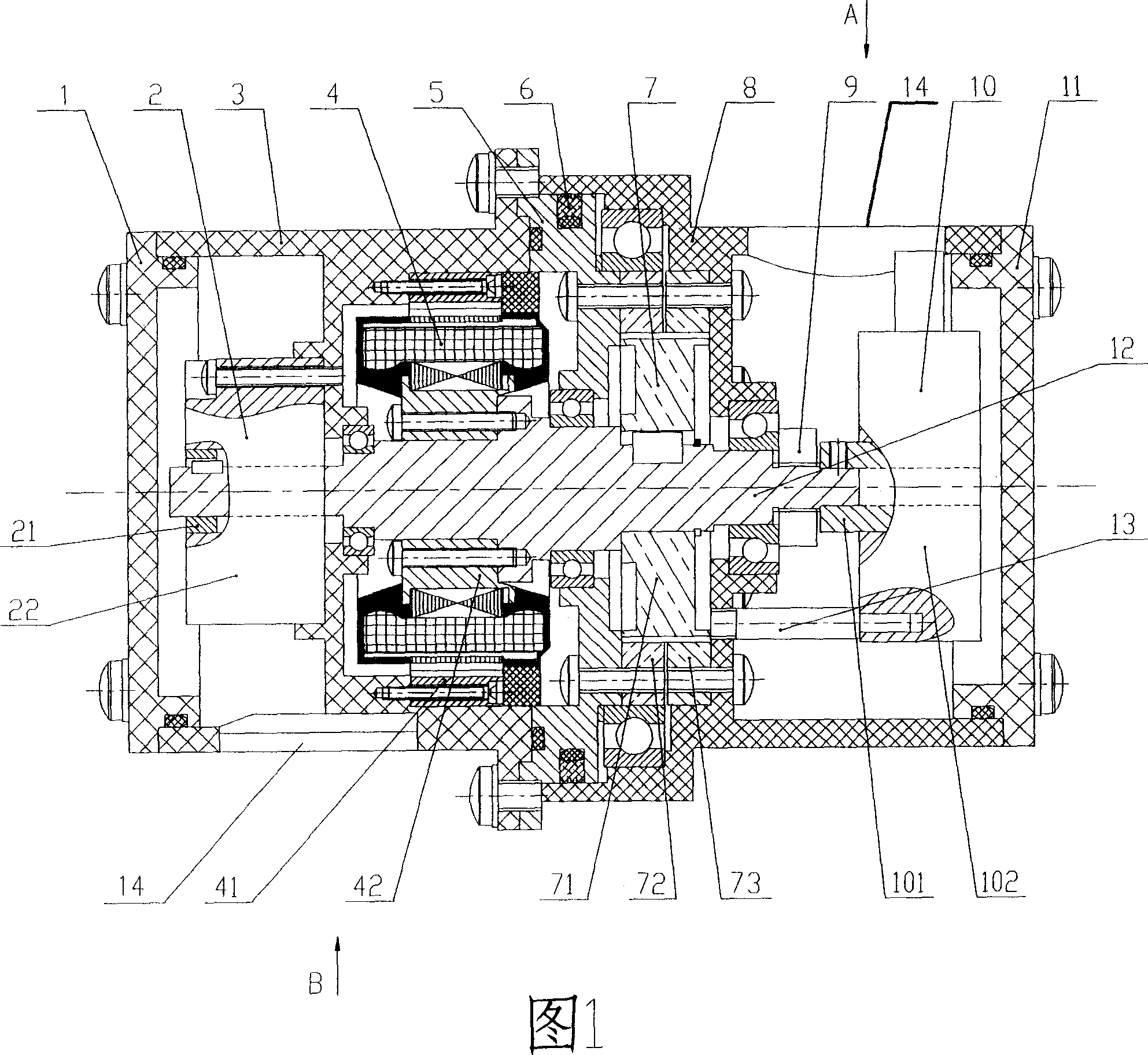
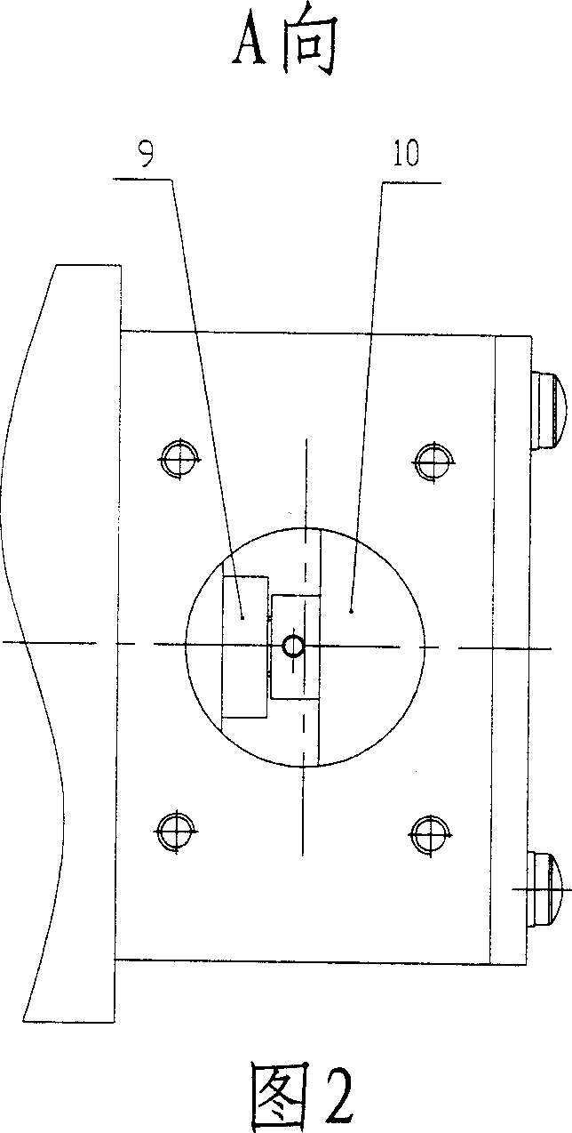
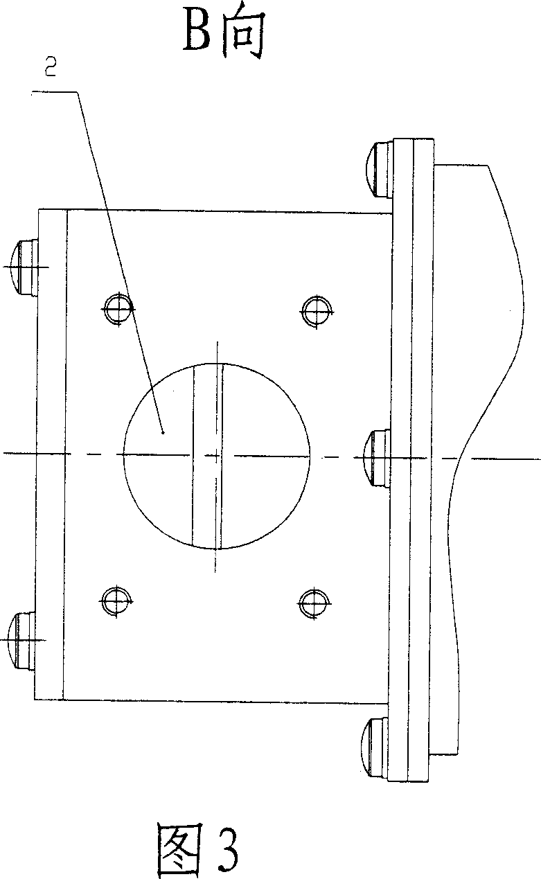
[0018] As shown in Figure 1, the present invention includes a stationary end housing 3, a moving and static housing transition piece 5, and a driven end housing 8. The central shaft 12 passes through the three in turn, and one end of the stationary end housing 3 is fixedly connected with a stationary end cover 1. The other end is connected with the dynamic and static housing transition piece 5, one end of the driven end housing 8 is fixedly connected with the driven end end cover 11, and the other end abuts on the dynamic and static housing transition piece 5. A brake 2, a torque motor assembly 4, a harmonic reducer assembly 7 and a rotary encoder 10 are sequentially sleeved on the central shaft 12 from left to right. The brake 2 is housed in the space formed by the stationary end cover 1 and the stationary end housing 3, and includes a power-on rotatable part 21 and a fixed bo...


PUM


Abstract

A rotary joint structure for the underwater electric manipulator is composed of a static casing with end cover, a movable casing with end cover, a transition part between said static and movable casings, a central axle passing through said first three, and such units on said central axle as brake, torque motor module, harmonic speed reducer module, rotary encoder and fastening nuts.

Description

technical field [0001] The invention relates to robot engineering, in particular to an underwater electric manipulator rotary joint structure used for marine development and sampling. Background technique [0002] At present, in the field of offshore oil and gas exploration and development, commercial underwater manipulators used for underwater operations are all driven by hydraulic pressure. Its advantages are high load / self-weight ratio, strong load capacity, and easy deep-sea sealing through pressure compensation. However, the hydraulic manipulator system is bulky and the energy conversion rate is low. Due to the limitation of components and the need for complex support systems, it is difficult to achieve miniaturization. In order to achieve highly mobile ocean sampling and efficient underwater operations, the submarine operation system will gradually develop from the current master / slave remote control operation to autonomous / semi-autonomous operation, that is, the auto...

Claims


Application Information

Patent Timeline
IPC IPC(8): B25J17/00
Inventor 张奇峰张艾群张竺英
Owner SHENYANG INST OF AUTOMATION - CHINESE ACAD OF SCI
Why Eureka
Try Eureka