Biophotosynthetic reactor apparatus and process for producing micro algae

A photosynthetic reactor and microalgae technology, applied in photobioreactors, stress-stimulated microbial growth methods, biochemical equipment and methods, etc., can solve problems such as inability to carry out all-weather annual production, uncontrollable production factors, and difficulties in intensive management , to achieve the effect of promoting photosynthesis, improving photosynthetic efficiency and saving water resources

Inactive Publication Date: 2007-10-03
北京中企绿歌生物技术中心
View PDF0 Cites 14 Cited by
  • Summary
  • Abstract
  • Description
  • Claims
  • Application Information

AI Technical Summary

Problems solved by technology

Open pool production cannot control production factors and is subject to natural conditions. In this way, it is impossible to carry out industrialized all-weather annual production
In the production process of the open pond, the water consumption is large, and the collection of microalgae consumes energy and a lot of labor, which makes the intensive management of production difficult.

Method used


Image

  • Biophotosynthetic reactor apparatus and process for producing micro algae
  • Biophotosynthetic reactor apparatus and process for producing micro algae
  • Biophotosynthetic reactor apparatus and process for producing micro algae

Examples


Embodiment 1

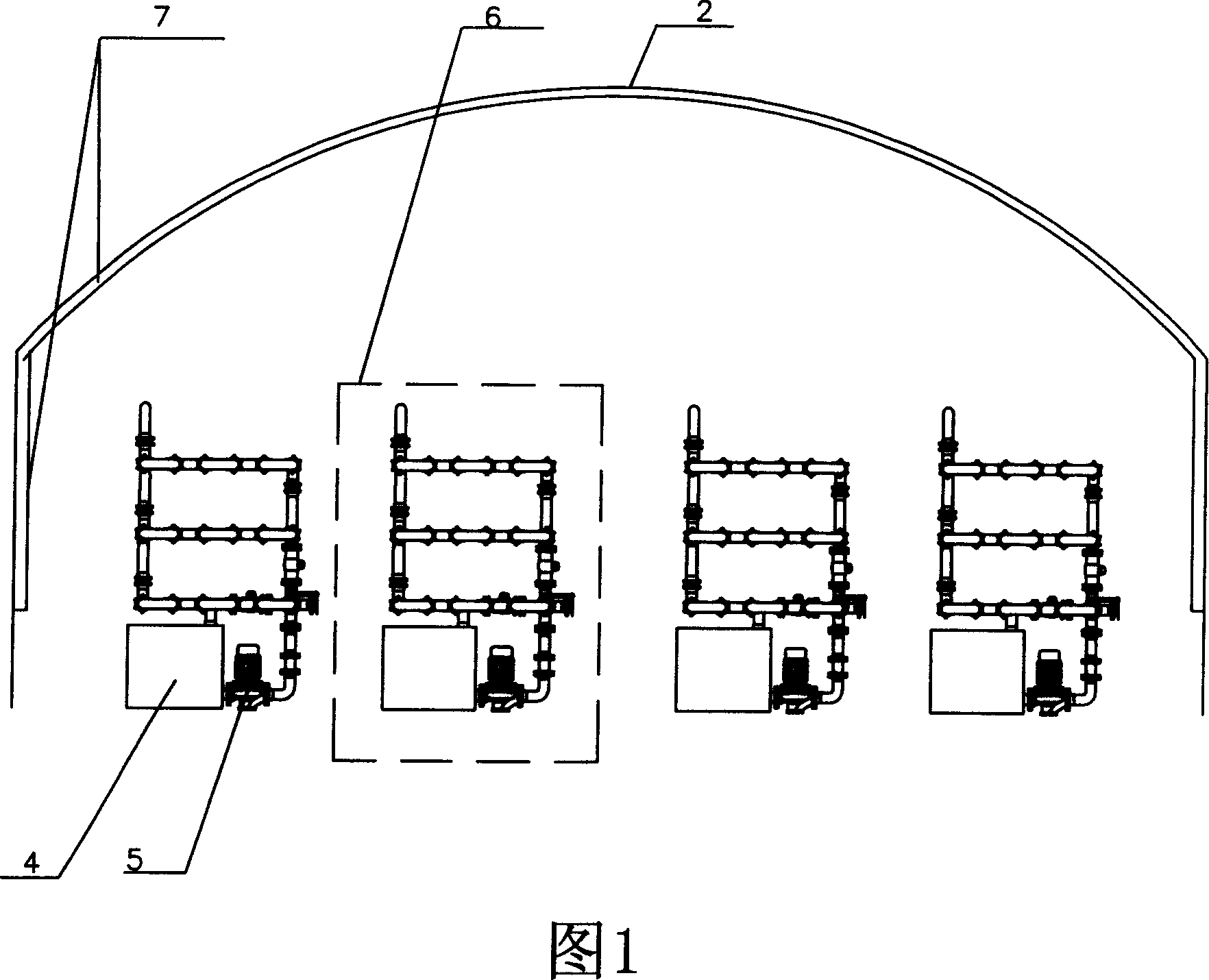
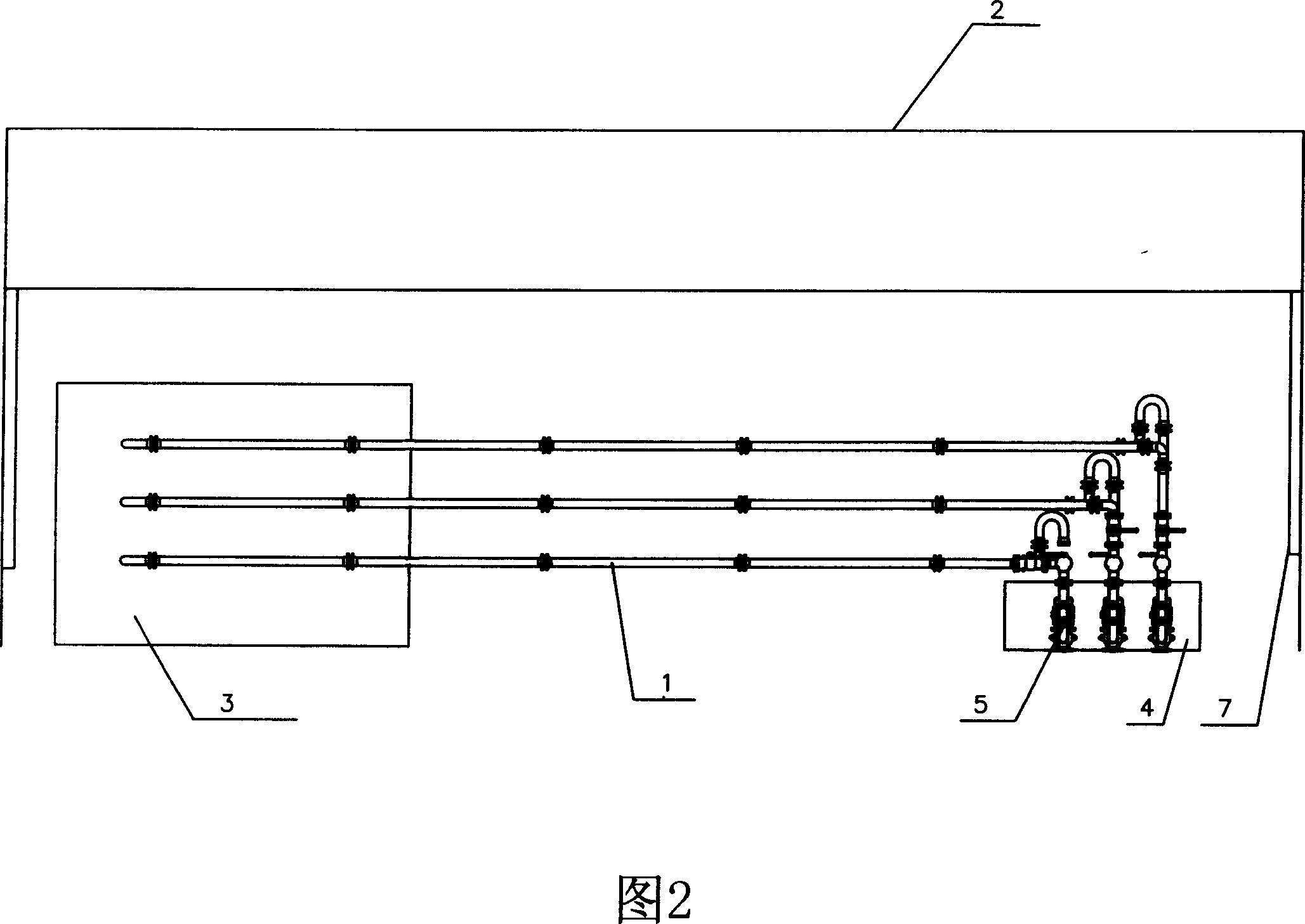
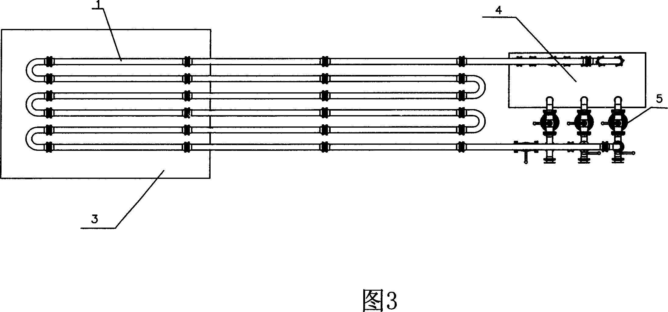
[0033] In the device for producing microalgae by a biological photosynthetic reactor of the present invention, the transparent photosynthetic greenhouse 2 is a light-converting film made of transparent rare-earth light-converting polypropylene, and the photosynthetic greenhouse 2 directly faces the sun to form a high-energy-gathering photoreceptor. Four closed circulation pipeline units 6 are installed in the photosynthetic greenhouse 2, and each closed circulation pipeline unit 6 includes three layers of closed circulation pipelines that are parallel to each other and individually circulated. The tubes and straight tubes are connected by U-shaped borosilicate glass pipelines, which communicate with each other. The inlet pump 5 is installed at the inlet of the pipeline, and is connected with the water source, the carbon dioxide source and the microalgae suspension tank 4, and the pipeline outlet is connected with the microalgae suspension tank 4. The microalgae suspension tank ...

Embodiment 2

[0041] The same as the device for producing microalgae in the biological photosynthetic reactor described in Example 1, the closed circulation pipeline is made of transparent polypropylene (PVC).

Embodiment 3

[0043] A process for producing chlorella using the bio-photosynthetic reactor described in Example 1 or 2 for producing microalgae, stocking chlorella in a closed circulation pipeline in a transparent photosynthetic greenhouse, and feeding the closed circulation pipeline 1 through an inlet pump 5 Add 6 tons of water (average 1.5 tons per circulation unit) and chlorella species to form a microalgae suspension, close the water source, pass carbon dioxide into the pipeline through the inlet pump 5, and control the chlorella in the closed circulation pipeline through the pump The suspension is in a turbulent state with a velocity of 1m / s. The chlorella suspension carries out photosynthesis in the closed circulation pipeline, grows and reproduces, and is controlled by the inlet pump 5, circulates between the closed circulation pipeline and the microalgae suspension tank, and passes through the temperature of the circulating water tank 3 and the photosynthetic greenhouse 2. The cont...


PUM


Abstract

The present invention is biophotosynthetic reactor apparatus and process for producing micro algae. Inside one transparent photosynthetic greenhouse, there are at least one closed transparent circulating pipeline unit with at least one layer of sealed circulating pipes made of high energy converging light-converting RE material, and light-converting plates or films of high energy converging light-converting RE material. Inside the sealed circulating pipes, chlorella is cultured. The present invention has full utilization of natural illumination, capacity of avoiding hetero microbe contamination, effective control of temperature and CO2 addition and high chlorella yield and quality.

Description

technical field [0001] The invention relates to a device and process for stocking microalgae, in particular to a device and process for producing microalgae by using a biological photosynthetic reactor. Background technique [0002] At present, open-air open ponds are commonly used to stock microalgae at home and abroad, similar to operating fish ponds. The suspended growth of algae is in direct contact with the external environment, and it is not easy to control the most appropriate process parameters. The water surface of the open-air open pond and the outside world are frequently heated. exchange. The outside atmosphere changes dramatically not only throughout the year, but also every day; especially in arid desert areas, where the temperature difference between morning and evening can reach more than ten degrees. Therefore, in many microalgae production devices in the world at present, the output is greatly reduced every low temperature season, and some cannot produce. ...

Claims


Application Information

Patent Timeline
Patent Type & Authority Applications(China)
IPC IPC(8): C12M1/42
CPCC12M41/10C12M21/02C12M23/06C12M23/18
Inventor 张长青田裕钊
Owner 北京中企绿歌生物技术中心
Why Eureka
Try Eureka