Device and method for monitoring guiding thread in knitting machine

A technology for knitting machines and yarn guides, which is applied to measuring devices, knitting, textiles and paper making, etc., can solve the problems of high cost, time-consuming maintenance work, difficulty in manufacturing yarn breakage detectors, etc., and achieve the effect of increasing costs.

Inactive Publication Date: 2010-06-30
FRAUNHOFER GESELLSCHAFT ZUR FOERDERUNG DER ANGEWANDTEN FORSCHUNG EV
View PDF9 Cites 0 Cited by
  • Summary
  • Abstract
  • Description
  • Claims
  • Application Information

AI Technical Summary

Problems solved by technology

[0004] As already stated, yarn tensioning devices and yarn breakage detectors are mostly mechanical in known operating knitting machines or circular knitting machines and are therefore subject to unavoidable wear and tear, which leads to time-consuming maintenance work in defined (time) intervals
Furthermore, the mentioned yarn breakage detectors are also difficult to manufacture and correspondingly expensive due to their mechanical design.

Method used


Image

  • Device and method for monitoring guiding thread in knitting machine
  • Device and method for monitoring guiding thread in knitting machine
  • Device and method for monitoring guiding thread in knitting machine

Examples


Embodiment Construction

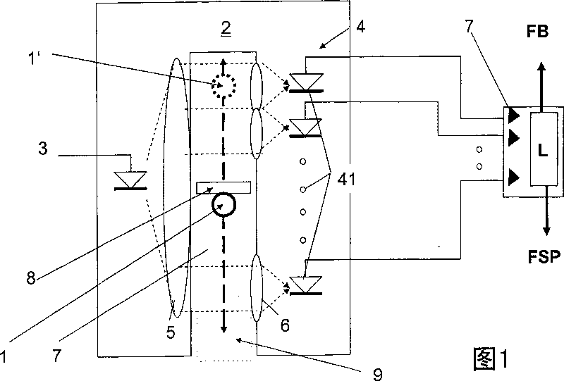
[0024] exist figure 1 A schematic diagram of the principle of a yarn sensor for monitoring the running of yarn in a knitting machine is shown in , which describes a cross-sectional view perpendicular to the extension line of the yarn passing through the device. It is assumed here that the yarn 1 is moved through a yarn feed direction which is oriented perpendicular to the drawing plane. The frame of the U-shaped structure shown around the position of the yarn 1 very schematically describes the optical sensor unit, which is formed in the form of a pair of fork-shaped optoelectronic devices. The fork-shaped optoelectronic device pair 2 has a light source 3 along one of its U-legs, which is configured in the form of a single-LED, a photodiode row or in the form of another light source of linear radiation and it on the other hand along its The further U-leg of the U-leg is provided with a photodetector arrangement 4 which, in the exemplary embodiment shown, consists of a combinat...


PUM


Abstract

The present invention describes a device and method for monitoring yarn guide in a knitting machine, wherein at least a yarn can be guided along the yarn transporting section freely with a given yarn tension, at least a unit supplying yarn along the yarn transporting section freely and a unit receiving and / or continuously guiding the yarn with the yarn tension, the invention is characterized in that an optical sensor unit is arranged along the free yarn transporting section for noncontactly detecting yarn, and the optical sensor unit generates a sensor signal, which effects on control or adjustment signal of said unit supplying yarn, and / or receiving and / or continuously guiding the yarn.

Description

technical field [0001] The invention relates to a device and a method for monitoring the yarn guidance in a knitting machine, wherein at least one yarn can be guided along a free yarn delivery section with a predeterminable yarn tension, with at least one The free yarn delivery section provides a unit for the yarn and a unit for receiving and / or feeding the yarn under yarn tension. Background technique [0002] Knitting machines and in particular circular knitting machines mechanically produce knitted goods or knitted fabrics which are partially made of more than 100 different yarns. Each individual yarn is fed into the knitting mechanism and thus into the knitting process by means of a so-called yarn feeder, wherein the yarn feed is uniform and uniform along all yarn feed strands and in a definite preset Yarn tension achieved. In order to ensure a necessary yarn tension for reliable knitting operation, each individual yarn feeder is provided with a mechanical yarn tension...

Claims


Application Information

Patent Timeline
IPC IPC(8): D04B35/10D04B35/14B65H59/10B65H63/02G01N21/898
Inventor 哈特维希·施托伊斯洛夫
Owner FRAUNHOFER GESELLSCHAFT ZUR FOERDERUNG DER ANGEWANDTEN FORSCHUNG EV
Why Eureka
Try Eureka