

Imaging lens
A camera lens and lens technology, applied in optical elements, optics, instruments, etc., can solve the problems of image plane variation and high manufacturing sensitivity, and achieve the effect of increasing the number of lenses and high performance
- Summary
- Abstract
- Description
- Claims
- Application Information
AI Technical Summary
Problems solved by technology
Method used
Image

Examples
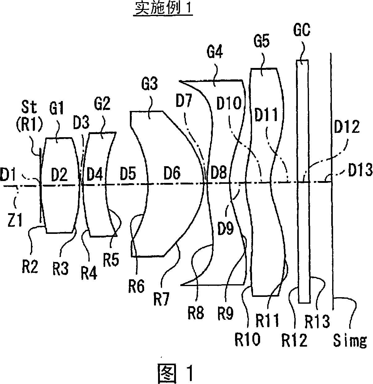
Embodiment 1
[0069] In the imaging lens according to Example 1, in addition to the second lens L2, both surfaces of the third lens L3, the fourth lens L4, and the fifth lens L5 are aspherical. In the basic lens data of FIG. 5(A), the numerical value of the radius of curvature near the optical axis is shown as the radius of curvature of these aspherical surfaces. Among the numerical values shown as aspheric surface data in Fig. 5 (B), the symbol "E" indicates that the data immediately following it is a "power exponent" with a base of 10, indicating that the exponential function will be obtained by the base 10. The indicated value is multiplied by the value preceding the "E". For example, if it is "1.0E-02", it means "1.0×10 -2 ".
[0070] As the aspheric surface data, the values of the respective coefficients Bi and KA in the formula of the aspheric surface shape represented by the following formula (A) are shown. More specifically, Z represents the length (mm) of a perpendicular lin...
PUM
 Abstract
Description
Claims
Application Information