Light emitting device

A light-emitting device and light-emitting element technology, which is applied in the direction of electrical components, electric solid-state devices, circuits, etc., can solve the problems of light-emitting diode chips with reduced luminous efficiency and low heat dissipation, and achieve the effects of good heat dissipation and improved acquisition efficiency

Inactive Publication Date: 2007-10-03
TOSHIBA LIGHTING & TECH CORP
View PDF2 Cites 9 Cited by
  • Summary
  • Abstract
  • Description
  • Claims
  • Application Information

AI Technical Summary

Problems solved by technology

[0003] In addition, in such a light-emitting diode device, a case is known in which a synthetic resin such as PPA (polyphthalamide) is used, but the thermal conductivity of this synthetic resin is, for example, about 0.3 W / m·K, and the heat dissipation is low. , so there is a problem that the luminous efficiency of the light-emitting diode chip decreases as the temperature rises

Method used


Image

  • Light emitting device
  • Light emitting device
  • Light emitting device

Examples


Embodiment Construction

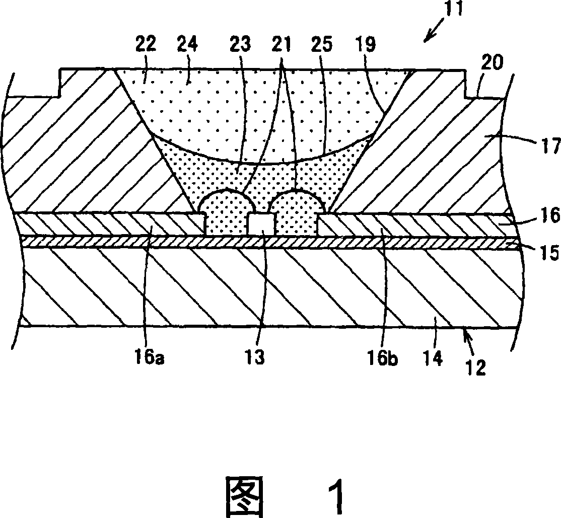
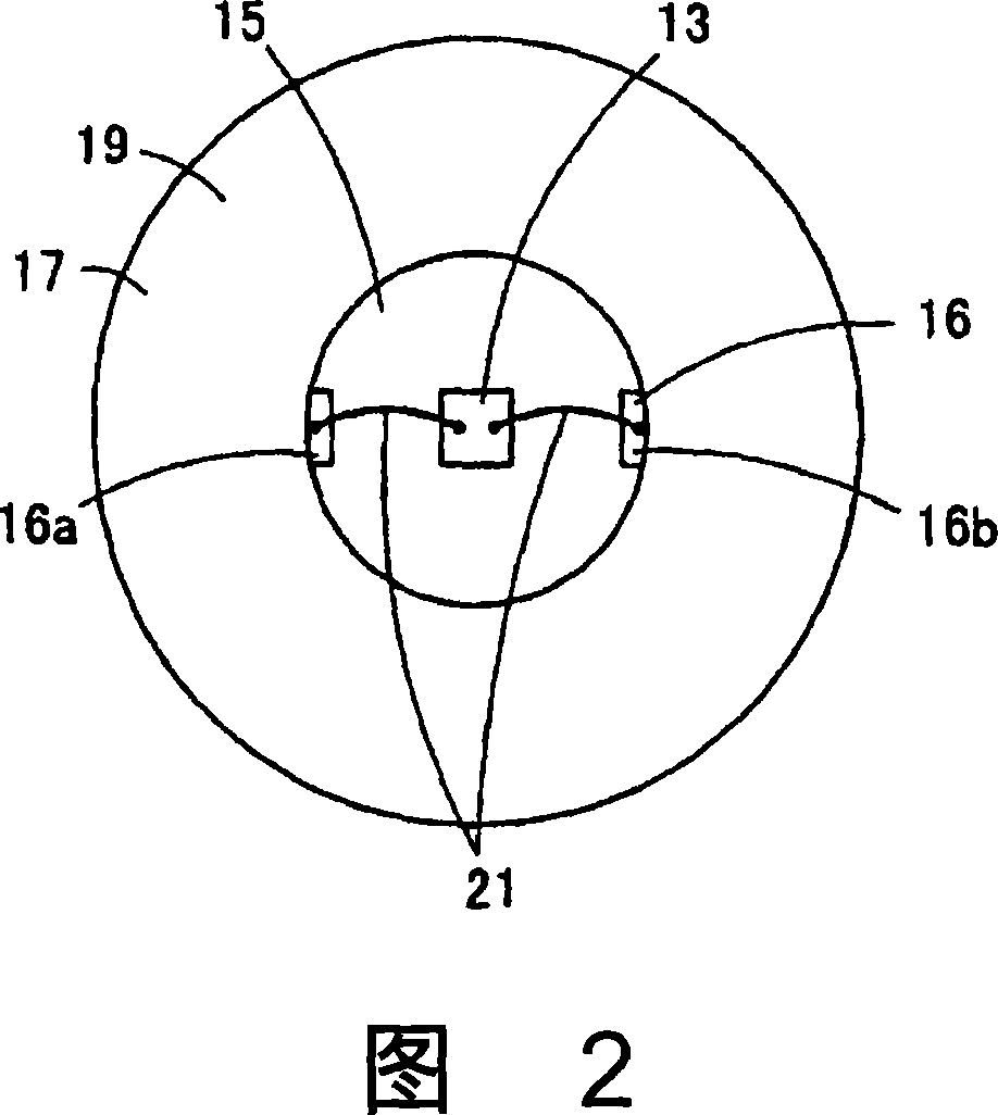
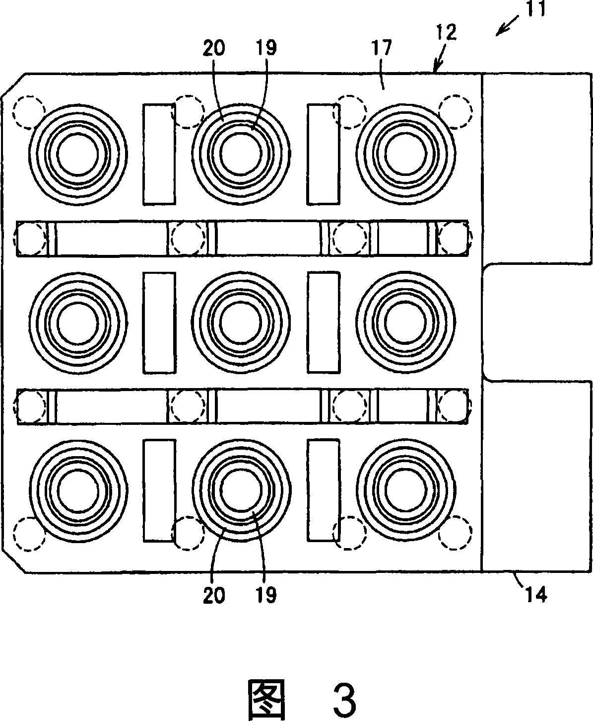
[0030] Hereinafter, an embodiment of the present invention will be described with reference to the drawings. 1 is a partially enlarged cross-sectional view of the light emitting device, FIG. 2 is a partially omitted enlarged front view of the light emitting device, FIG. 3 is a front view of the light emitting device, and FIG. 4 is an enlarged cross-sectional view of the light emitting device.

[0031] In the figure, the light-emitting device 11 includes a light-emitting module 12 that is detachably attached to a light-emitting device main body (not shown), such as a lighting fixture main body, for example. In the light emitting module 12 , a plurality of chip-shaped solid light emitting elements serving as light emitting elements, that is, light emitting diode elements (light emitting diode chips) 13 are arranged in a matrix. The light emitting diode element 13 is made of, for example, a gallium nitride (GaN)-based semiconductor or the like that emits blue light with a lumines...


PUM


Abstract

An object of the present invention is to provide a light-emitting device in which the light-acquisition efficiency of a light-emitting element is less likely to be lowered even if a resin substrate having good thermal conductivity is used. The first aspect of the present invention is characterized by comprising a resin substrate 14 having a thermal conductivity of 1.0 to 9.0 W / m·K, a white insulating layer 15 provided on the resin substrate, and a circuit pattern provided on the insulating layer. Layer 16, light-emitting element 13 disposed on the insulating layer and electrically connected to the circuit layout layer.

Description

technical field [0001] The present invention relates to a light emitting device using a light emitting element. Background technique [0002] Conventionally, as an example of a light emitting diode device, a surface mount type light emitting diode device is known in which a case (groove) in which a light emitting diode chip is placed is filled with synthetic resin and the light emitting diode chip is sealed in the case (see Patent Document 1). [0003] In addition, in such a light-emitting diode device, a case is known in which a synthetic resin such as PPA (polyphthalamide) is used, but the thermal conductivity of this synthetic resin is, for example, about 0.3 W / m·K, and the heat dissipation is low. , so there is a problem that the luminous efficiency of the light emitting diode chip decreases as the temperature rises. [0004] In addition, in the known light-emitting diode device of the second prior art, in order to suppress its temperature rise, a heat dissipation hole ...

Claims


Application Information

Patent Timeline
Patent Type & Authority Applications(China)
IPC IPC(8): H01L33/00H01L33/48H01L33/56H01L33/60H01L33/64
CPCH01L2224/48091H01L2924/181
Inventor 三瓶友广野木新治
Owner TOSHIBA LIGHTING & TECH CORP
Why Eureka
Try Eureka