Brushless exciting controller

A controller and excitation technology, which is applied in the control system, generator control, generator control through magnetic field changes, etc., can solve the problems of AC brushless excitation generator without excitation control device, etc., to improve load and dynamic performance, Improved strong excitation capability and fewer failures

Inactive Publication Date: 2007-10-03
CNR SHIP & MARINE ENG DEV CO LTD
View PDF0 Cites 8 Cited by
  • Summary
  • Abstract
  • Description
  • Claims
  • Application Information

AI Technical Summary

Problems solved by technology

[0003] The present invention provides a brushless excitation controller in order to solve the problem that the existing AC brushless excitation generator, especially the AC brushless excitation generator used for the auxiliary system of a diesel locomotive, does not have a suitable excitation control device

Method used


Image

  • Brushless exciting controller

Examples


Embodiment Construction

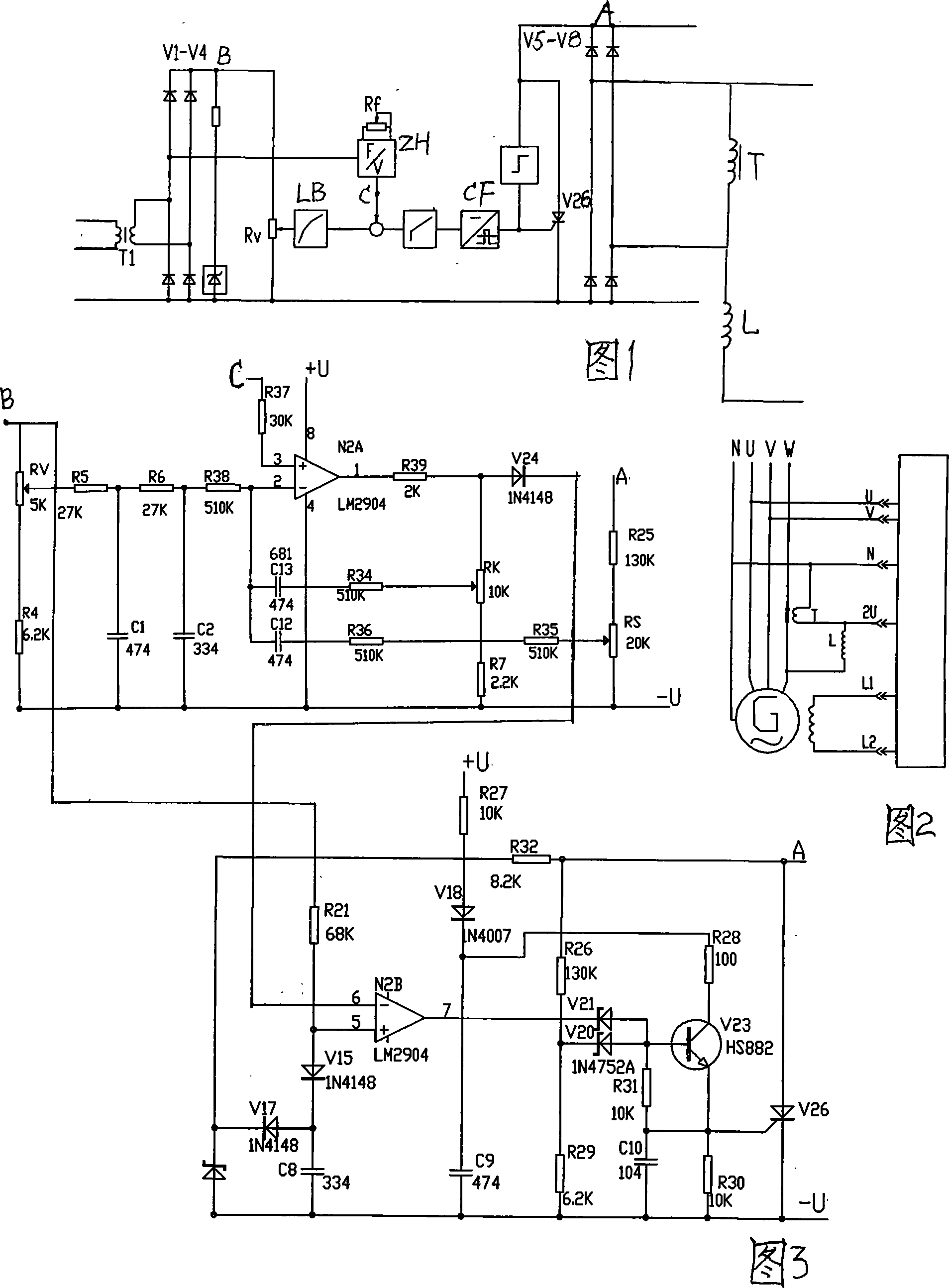
[0011] The brushless excitation controller includes an excitation current acquisition circuit composed of a reactor L and a current transformer T connected in series. The two ends of the current transformer T are connected in parallel with an excitation rectifier bridge composed of diodes V5-V8. The DC current of the excitation rectifier bridge The output terminal is connected in parallel with the thyristor V26, and its control pole is connected with the on-off control circuit of the thyristor V26; the on-off control circuit of the thyristor V26 includes a transformer T1, and the secondary end of the transformer T1 is connected with diodes V1-V4 The detection rectifier bridge is formed, the DC output end of the detection rectification bridge is connected in parallel with an adjustable resistance RV, and the adjustment output end of the adjustable resistance RV is connected to the inverting input end of the operational amplifier N2A through the filter circuit LB; the pass through...


PUM


Abstract

A brushless excitation controller is prepared as forming excitation voltage-current signal collection circuit by series-connecting reactor and current mutual inductor, parallel-connecting excitation rectification bridge formed by diodes to two ends of current mutual inductor, parallel-connecting thyristor to DC output end of excitation rectification bridge and connecting control electrode of said bridge to on-off control circuit of said thyristor.

Description

technical field [0001] The invention relates to an excitation control device for a brushless excitation generator, in particular to a brushless excitation controller. The brushless excitation controller is used to control the voltage output of the AC brushless excitation generator with the characteristic of constant voltage frequency ratio, so as to ensure that the generator can operate with constant magnetic flux under any speed condition of the diesel engine, and improve the efficiency and reliability of the motor. sex. Background technique [0002] Today, the use of AC drive in the main and auxiliary systems of diesel locomotives has become the main trend in the development of diesel locomotives. At present, the AC transmission of domestic diesel locomotives is still in its infancy. All OEMs have begun to explore and experiment with the AC of auxiliary systems. An independent power supply system on the locomotive should complete the functions of the previous hydrostatic ...

Claims


Application Information

Patent Timeline
Patent Type & Authority Applications(China)
IPC IPC(8): H02P9/10H02P9/32
Inventor 徐龙堂李国锋陈建峰马连风
Owner CNR SHIP & MARINE ENG DEV CO LTD
Why Eureka
Try Eureka