Method and equipment for machining bent pipe with small R

A processing device and pipe bending technology, applied in the field of mechanical processing, to achieve the effect of feasible method, obvious technological advancement and strong practicability

Inactive Publication Date: 2007-10-10
BAIYUN AUTOCARS PIPES MAKING SHANGHAI
View PDF0 Cites 33 Cited by
  • Summary
  • Abstract
  • Description
  • Claims
  • Application Information

AI Technical Summary

Problems solved by technology

[0010] The purpose of the present invention is to focus on solving the problems of the extensibility of the steel pipe material, the ellipticity of the bend, and the fullness of the bend section on the basis of the existing common pipe bending pr

Method used


Image

  • Method and equipment for machining bent pipe with small R
  • Method and equipment for machining bent pipe with small R
  • Method and equipment for machining bent pipe with small R

Examples


Embodiment Construction

[0031] The present invention will be further described below in conjunction with the accompanying drawings and typical embodiments.

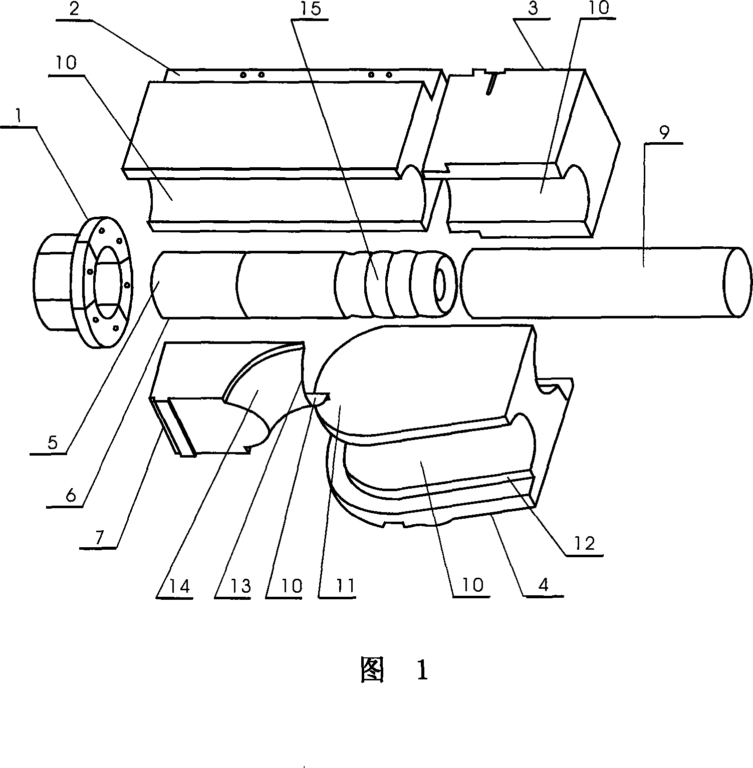
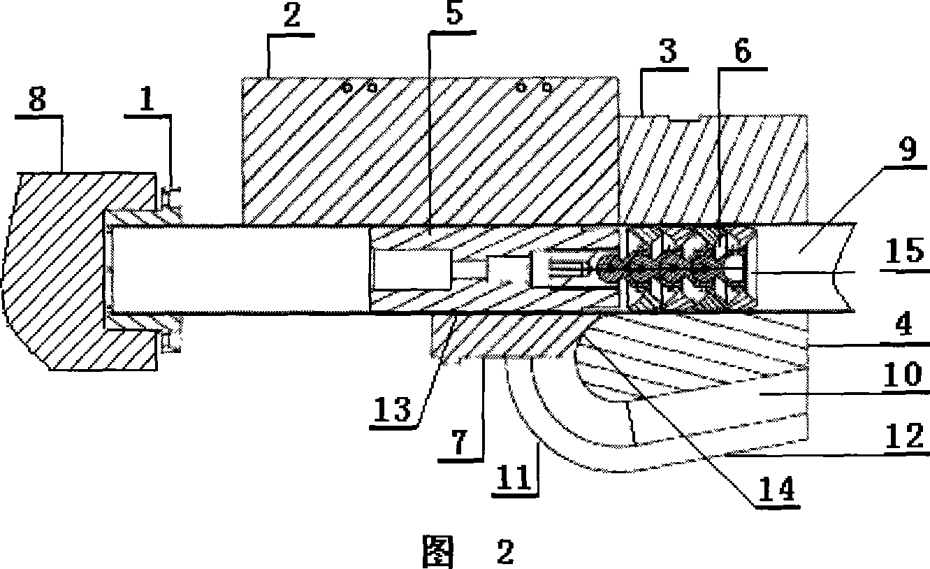
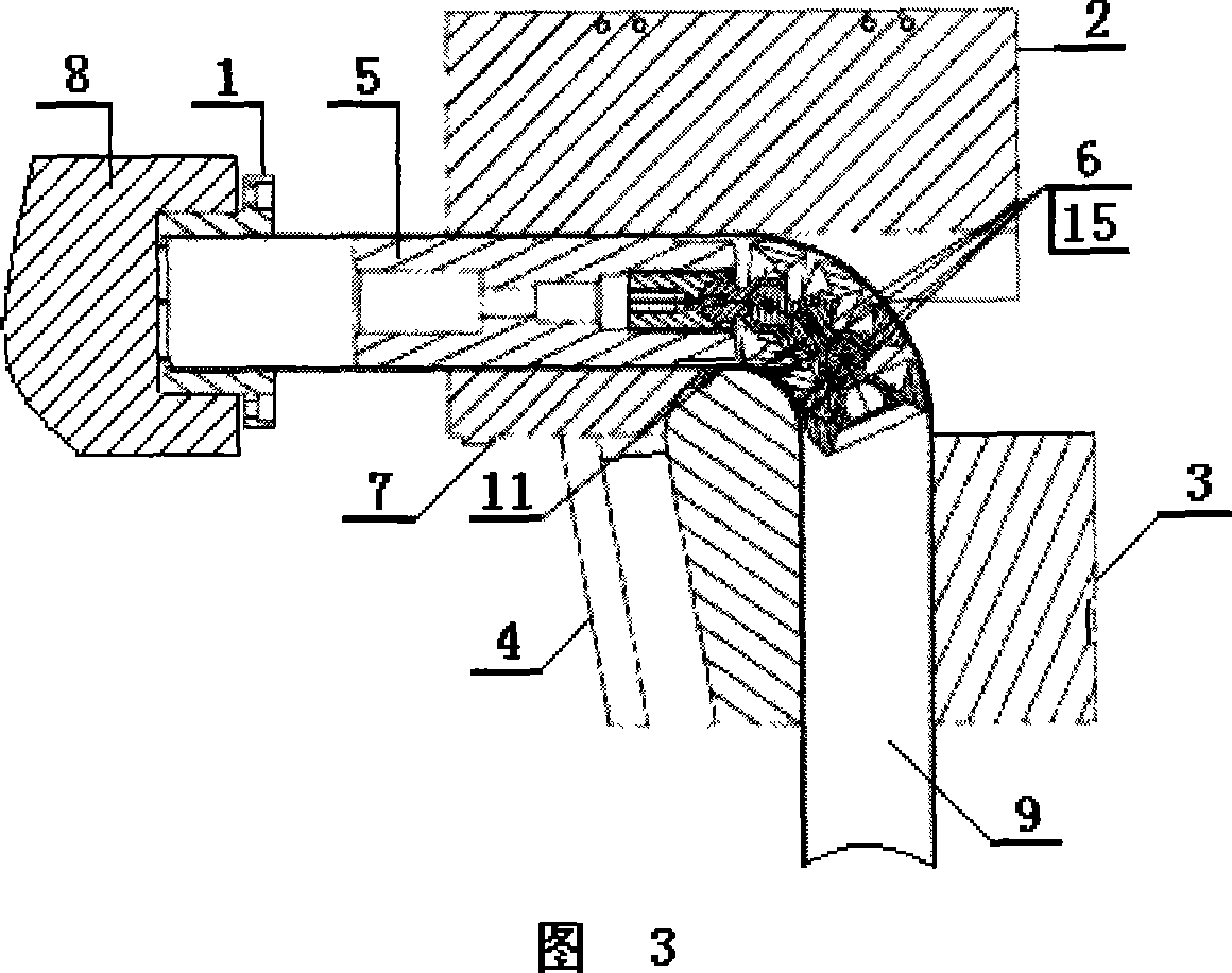
[0032]In Fig. 1, Fig. 2 and Fig. 3, the processing device of the small R bend pipe of the present invention mainly includes a three-dimensional numerical control pipe bending machine with hydraulic and servo motor drive mechanism, a forming bending mold and accessories, and a forming bending mold It contains an eight-jaw clamping mold 1, a master mold 2, a clamping mold 3, and a diameter mold 4. The auxiliary parts mainly include an active joint 6 with a core rod 5, an anti-wrinkle mold 7 and a push trolley 8. Wherein: the diameter die 4 is R-shaped, and the continuous edge formed by the edge of the convex semicircular R-shaped curved front end portion 11 and the edges of the inclined portions 12 on both sides is provided with a side surface corresponding to the outer diameter of the workpiece 9 The semi-circular arc noodle-shaped limiting groove 10...


PUM


Abstract

An apparatus for machining a small-radius elbow pipe is composed of a numerally controlled 3D pipe bending machine with a drive unit having hydraulic and servo motors, a pipe bending die set consisting of 8-jaw clamping die, diameter die, clamping die and copying die, and the accessory with movable joint having mandrel and anti-crease die. Its technology is also disclosed.

Description

Technical field [0001] The invention relates to the technical field of mechanical processing, in particular to a processing method and a device for manufacturing a metal hollow tube into a small R-bend tube. Background technique [0002] Small R bends are a special process for bending steel pipes. Any bending where the ratio of the radius R of the steel pipe bend to the outer diameter of the workpiece ФD is less than 1.2 and greater than 0.8 is collectively referred to as small R radius bending: [0003] W=R / ФD [0004] 0.8≤W≤1.2 [0005] Ovality means that under small R-radius bends, the bent workpiece is elliptical due to deformation at the bend and cannot maintain the original roundness of the steel pipe. Generally, the ratio F of the difference between the maximum diameter of the ellipse MaxФD and the minimum diameter MinФD to the nominal outer diameter of the workpiece ФD is defined as the ellipticity. The ellipticity is ideally belo...

Claims


Application Information

Patent Timeline
IPC IPC(8): B21D9/12B21D9/16B21D37/10B21D37/12
Inventor 姚荣庆孙强柯若飞
Owner BAIYUN AUTOCARS PIPES MAKING SHANGHAI
Why Eureka
Try Eureka