
Joint controller of service brake of auto car and relaxed speed device, and controlling method

A main brake and automobile braking technology, applied in the joint control technology field of the braking system, can solve the problems of over-braking or under-braking, increasing the labor intensity of the driver, affecting ride comfort, etc., and achieve the goal of reducing heat load Effect

Inactive Publication Date: 2007-10-10
JIANGSU UNIV
View PDF2 Cites 37 Cited by
  • Summary
  • Abstract
  • Description
  • Claims
  • Application Information

AI Technical Summary

Problems solved by technology

However, since the braking power provided by the retarder itself is relatively small, the braking effect of the retarder alone cannot meet the requirements for the car to run stably on a long slope.
[0004] The independent control of the main brake of the braking system and the braking device including the eddy current retarder and the engine exhaust retarder has the following problems: 1. The various devices of the braking system require certain operations by the driver. Moreover, this operation is usually different from the traditional braking operation mode. In addition to increasing the driver's labor intensity, it is also easy to cause misoperation during braking.
2. The auxiliary braking device of the braking system usually has a relatively small braking power. In the case of a car that requires a large braking power, the driver needs to operate multiple auxiliary braking devices.
3. The independent operation of each device in the braking system is not conducive to the cooperation and coordination between the vehicles during the braking process, and it is easy to cause over-braking or insufficient braking, which affects the driving comfort of the car

Method used


Image

  • Joint controller of service brake of auto car and relaxed speed device, and controlling method
  • Joint controller of service brake of auto car and relaxed speed device, and controlling method
  • Joint controller of service brake of auto car and relaxed speed device, and controlling method

Examples


Embodiment Construction

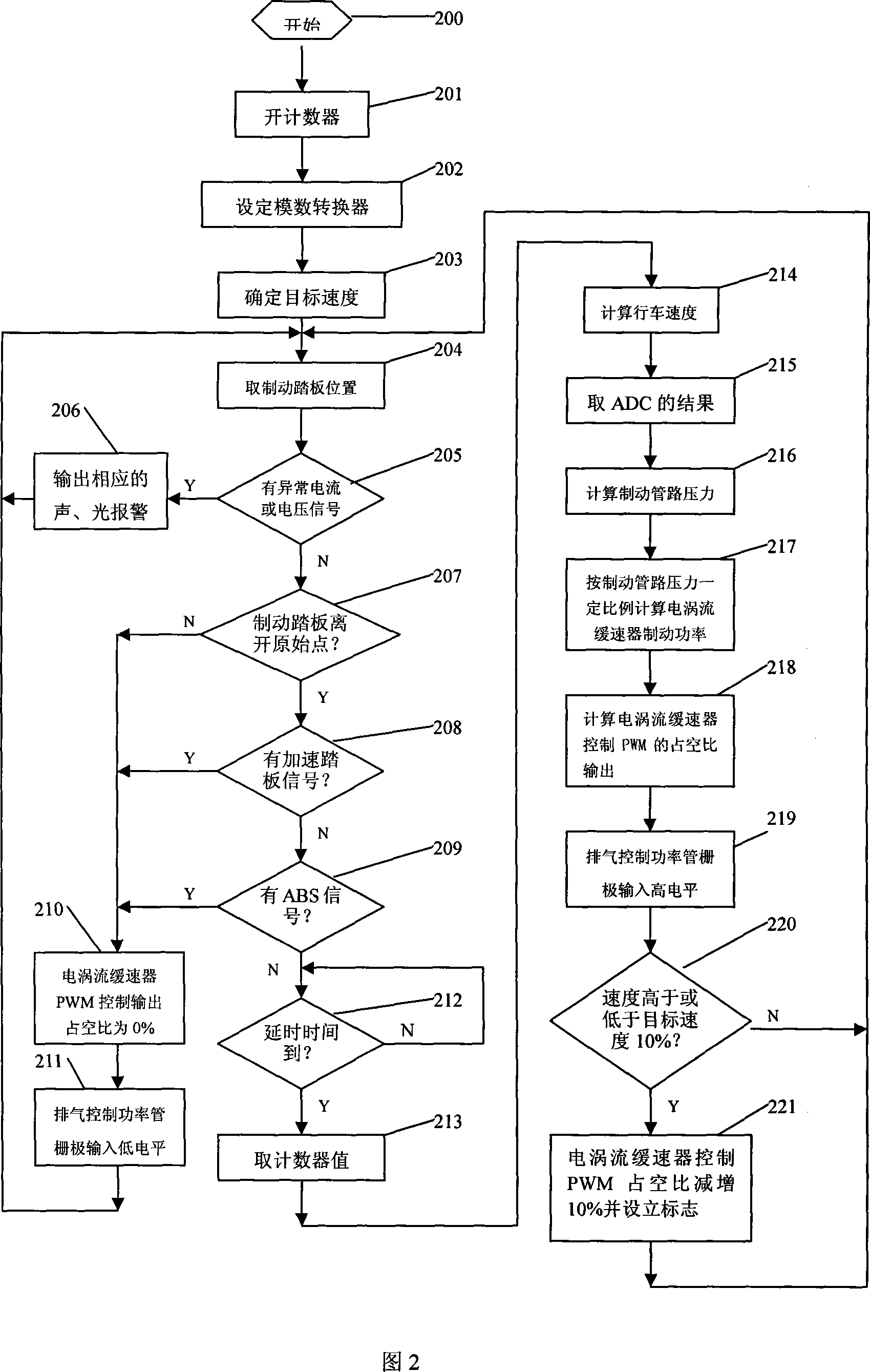
[0023] After the automobile is equipped with the combined controller of the main brake and the retarder of the present invention, the driver depresses the brake pedal in the traditional mode of operation when the driver needs to decelerate and brake, and the combined controller adopts a fully automatic The method controls the output torque of the eddy current retarder and controls whether the engine exhaust retarder participates in braking.

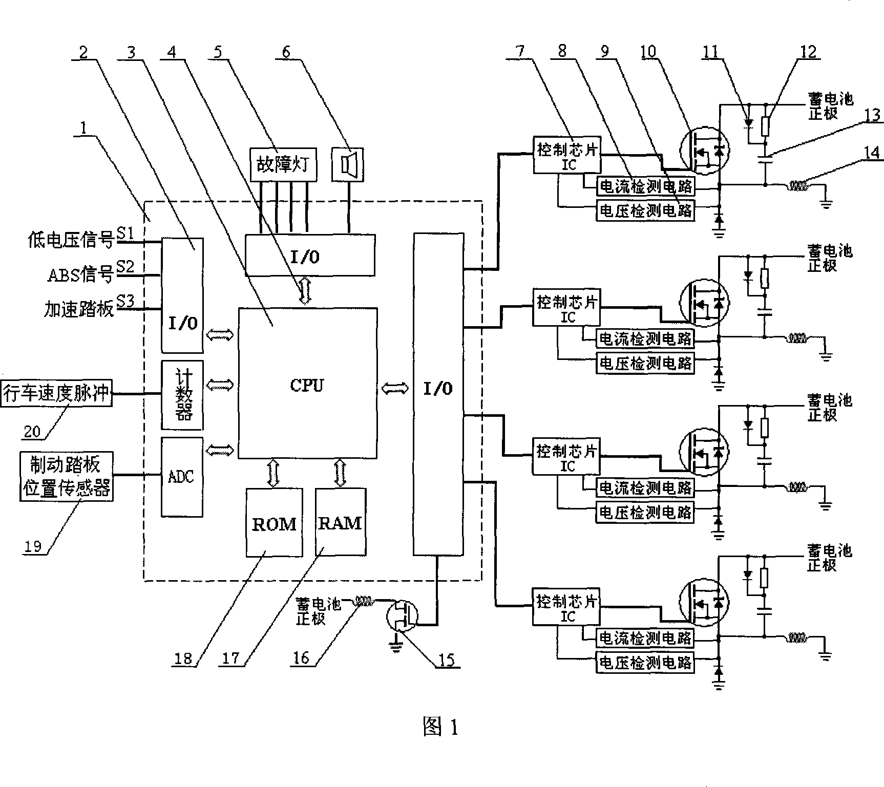
[0024] As shown in Figure 1, the microcomputer (1) collects the driving speed signal (20), the position signal (19) of the brake pedal, the low voltage signal S1, the ABS signal S2 and the accelerator pedal signal S3 in real time, and calculates the brake pedal signal S3 required by the automobile. The size of the power is converted into a PWM control signal with an appropriate duty ratio in time, and is transmitted to the drive device (7) through the internal bus (3) from the input / output interface (2) to control the on-off and on-off of ...


PUM


Abstract

A controller for the master brake of car and the decelerator including electric eddy one and engine exhaust one is composed of microcomputer, the driver unit for the electric eddy decelerator, the driver for the electromagnetic valve of engine exhaust decelerator, power switching module, feedback detecting circuit, and sound-light alarm circuit. Its control method is also disclosed.

Description

technical field [0001] The invention relates to an automotive electronic control product, which is suitable for the joint control technology of the braking system composed of the main brake of the transport vehicle and the auxiliary braking device including the eddy current retarder and the exhaust retarder of the engine. Background technique [0002] At present, road transport vehicles are restricted by regulations and need to be equipped with auxiliary braking systems. Chinese patent ZL01129767.0 announces an "Adjustment method for vehicle eddy current deceleration", its purpose is to adjust the deceleration method of vehicle eddy current retarder based on power electronics technology, this method can make the eddy current braking force in almost Stepless adjustment is made within the range from the minimum value of zero to the maximum value, which is easy to operate and has good stability. Chinese patent ZL200510034403.9 announces another "eddy current retarder drive con...

Claims


Application Information

Patent Timeline
Patent Type & Authority Applications(China)
IPC IPC(8): B60L7/28
Inventor 何仁赵迎生
Owner JIANGSU UNIV
Learn More