Tower type dual-purpose machine for lifting and raw material disposal

A tower-type lifting and distributing technology, which is applied in cranes, building materials processing, construction, etc., can solve problems such as unsafe, automatic distributing, and increased lifting weight, etc., and achieves the effect of convenient use and simple structure

Inactive Publication Date: 2007-10-10
李渊河
View PDF1 Cites 5 Cited by
  • Summary
  • Abstract
  • Description
  • Claims
  • Application Information

AI Technical Summary

Problems solved by technology

This device for transporting concrete on a construction tower crane overcomes the disadvantages of the concrete distribution crane that achieves horizontal displacement by changing the included angle of the boom because of its small amplitude range and limited application range.
The device for transporting concrete on the building tower crane has a certain distance between the discharge pipe and the slewing tower body when the elbow with pins is completely folded together. Within this range, the device for transporting concrete cannot automatically distribute materials; Yes, when the elbow with pin is fully retracted, the discharge pipe and hose are suspended in the air only through the auxiliary block, that is, they are suspended in the air through a movable hinge point, and the discharge pipe and hose are easy to shake back and forth. When it is heavy, it may hit the crane, which is not safe; in addition, when the elbow with the pin is fully retracted, the elbow with the pin, the discharge pipe and the hose are all located on the side of the slewing tower on the opposite side of the counterweight. Therefore, when lifting, it is necessary to configure counterweights for elbows, discharge pipes and hoses to increase the weight of the lifting; especially if the device for conveying concrete on the building tower crane is to be used for lifting, it must be Bend pipes, discharge pipes and hoses are retracted to the workbench, which is inconvenient to use and takes up space on the workbench

Method used


Image

  • Tower type dual-purpose machine for lifting and raw material disposal
  • Tower type dual-purpose machine for lifting and raw material disposal
  • Tower type dual-purpose machine for lifting and raw material disposal

Examples


Embodiment 1

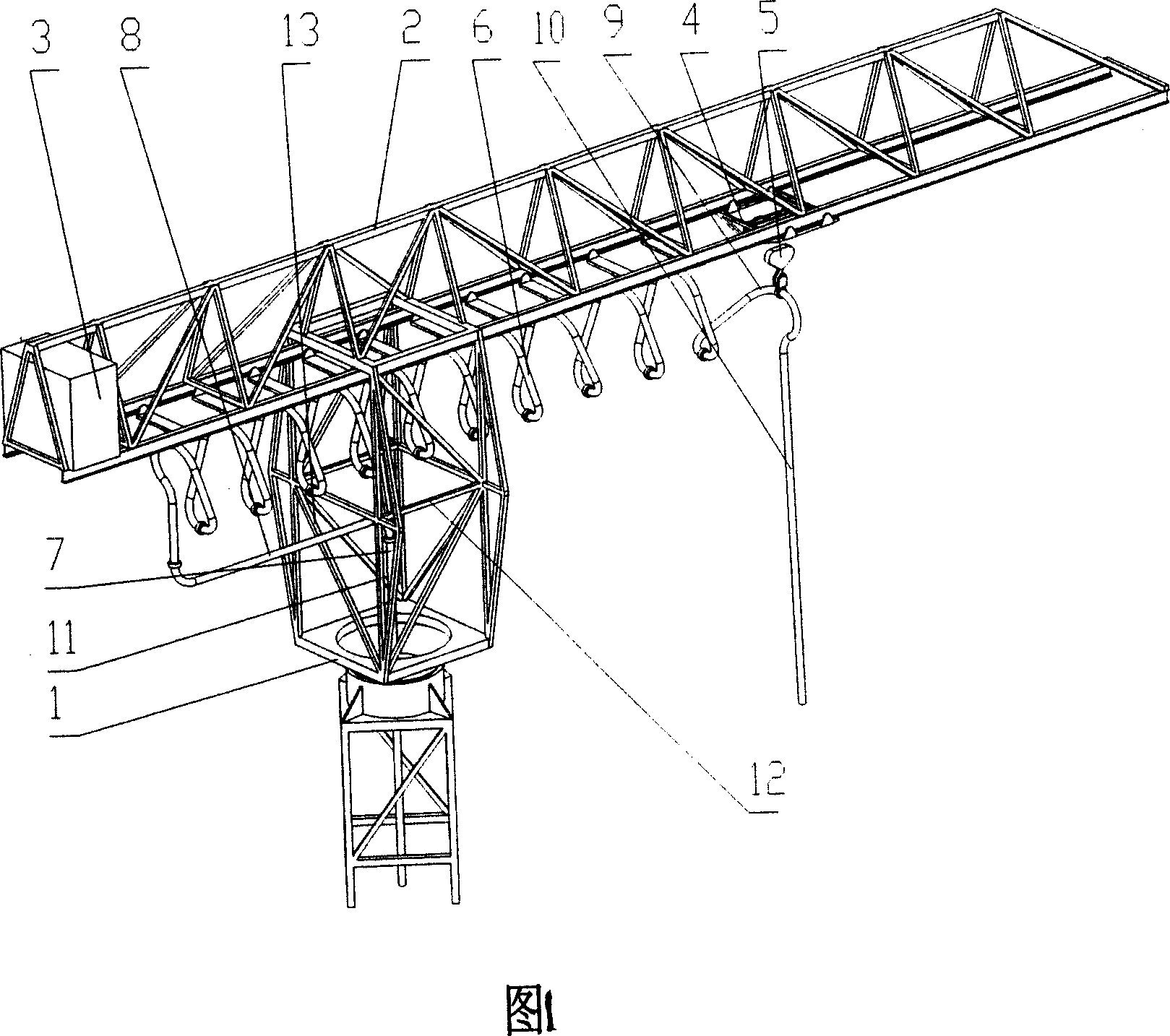
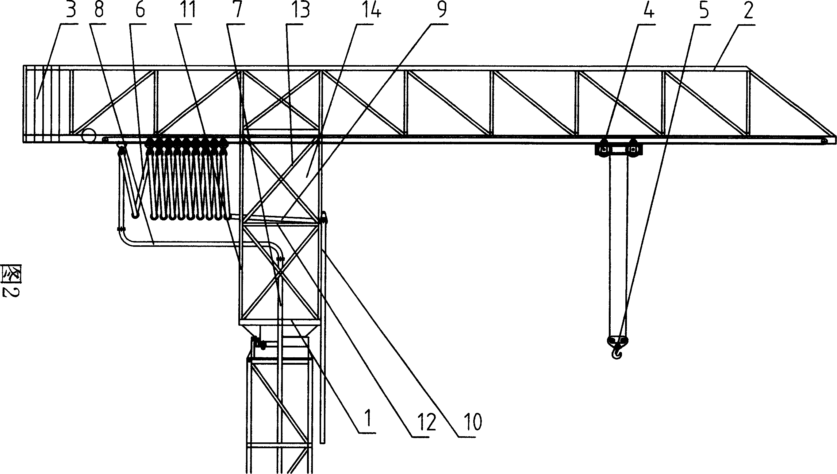
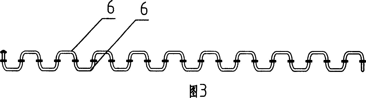
[0018] As shown in Figures 1 to 4, the tower-type lifting and distributing dual-purpose machine includes a slewing tower body 1, a boom 2 installed on the slewing tower body 1, a counterweight 3 installed on the boom 2 and a pulley 4. Concrete pump (not shown), concrete conveying pipe, hook 5 is provided on the tackle 4, the concrete conveying pipe includes the first curved pipe 6, the long straight pipe 7 installed in the tower body, connected with the long straight pipe 7 The second curved pipe 8 and the second curved pipe 8 are movably connected with the first curved pipe 6 at one end of the input concrete, and are also movably connected with the discharge pipe 9 on the first curved pipe 6 at the output concrete end, and the discharge pipe 9 Also flexibly connect flexible pipe 10 on it. Adjacent first curved pipes 6 are directly socketed end to end, and each section of first curved pipes 6 is movably installed on the boom 2 . Each first curved pipe 6 has a U-shaped project...

Embodiment 2

[0022] As shown in Figure 5, different from Embodiment 1, a reinforcing rod 17 is respectively arranged on both sides of the moving direction of the tackle in the rectangular frame of the first rectangular supporting space, and the reinforcing rod 17 is connected to the bottom of the first rectangular supporting space. The side 18 and the side 19 form a fourth triangular support space 20; the empty space is a trapezoidal space 22 formed between the reinforcement bar 17, the bottom 18 and the top 21 of the first rectangular support space.


PUM


Abstract

A tower crane used also for material distribution, especially for concrete distribution, is composed of a rotary tower body, a hoisting arm, the counterweight and carriage installed to said hoisting arm, a concrete pump, a hanging hook fixed to said carriage, and a concrete delivering pipe consisting of elbow pipes, jointers, and the discharge pipe.

Description

technical field [0001] The invention relates to a construction machine, in particular to a tower crane and concrete distributing dual-purpose machine composed of a tower crane and a concrete distributing machine. Background technique [0002] In building construction, when concrete casting and distributing high-rise buildings, a method often used is to use a concrete delivery pump to deliver concrete. In the utility model with the patent number 96227235.3 and the name of the device for conveying concrete on the construction tower crane, a utility model including a pump station, a straight pipe, a movable ferrule, an upper support frame, a lower support frame, a working platform, a curved pipe, a fixed A special concrete distribution device composed of ferrules. This device for transporting concrete on a building tower crane overcomes the disadvantages of a concrete distribution crane that achieves horizontal displacement by changing the included angle of the boom because of...

Claims


Application Information

Patent Timeline
Patent Type & Authority Applications(China)
IPC IPC(8): B66C25/00B66C23/16E04G21/04
CPCE04G21/04B66C23/26E04G21/0427
Inventor 李渊河
Owner 李渊河
Why Eureka
Try Eureka