Synchronous zooming device for laser lighting device

A technology of synchronous zooming and illuminator, which is applied in the field of laser illuminator, can solve problems such as inability to realize synchronous zooming, and achieve the effect of simple and reliable signal feedback mechanism, convenient operation and high precision

Active Publication Date: 2007-10-10
山东神戎电子股份有限公司
View PDF0 Cites 7 Cited by
  • Summary
  • Abstract
  • Description
  • Claims
  • Application Information

AI Technical Summary

Problems solved by technology

But this adjustment is independent of the lens. After adjusting the focal length of the lens, the illumination angle of the illuminator needs to be adjusted separately. The synchronous zoom of the two cannot be realized, and there are still many inconveniences in the application.

Method used


Image

  • Synchronous zooming device for laser lighting device
  • Synchronous zooming device for laser lighting device
  • Synchronous zooming device for laser lighting device

Examples


Embodiment Construction

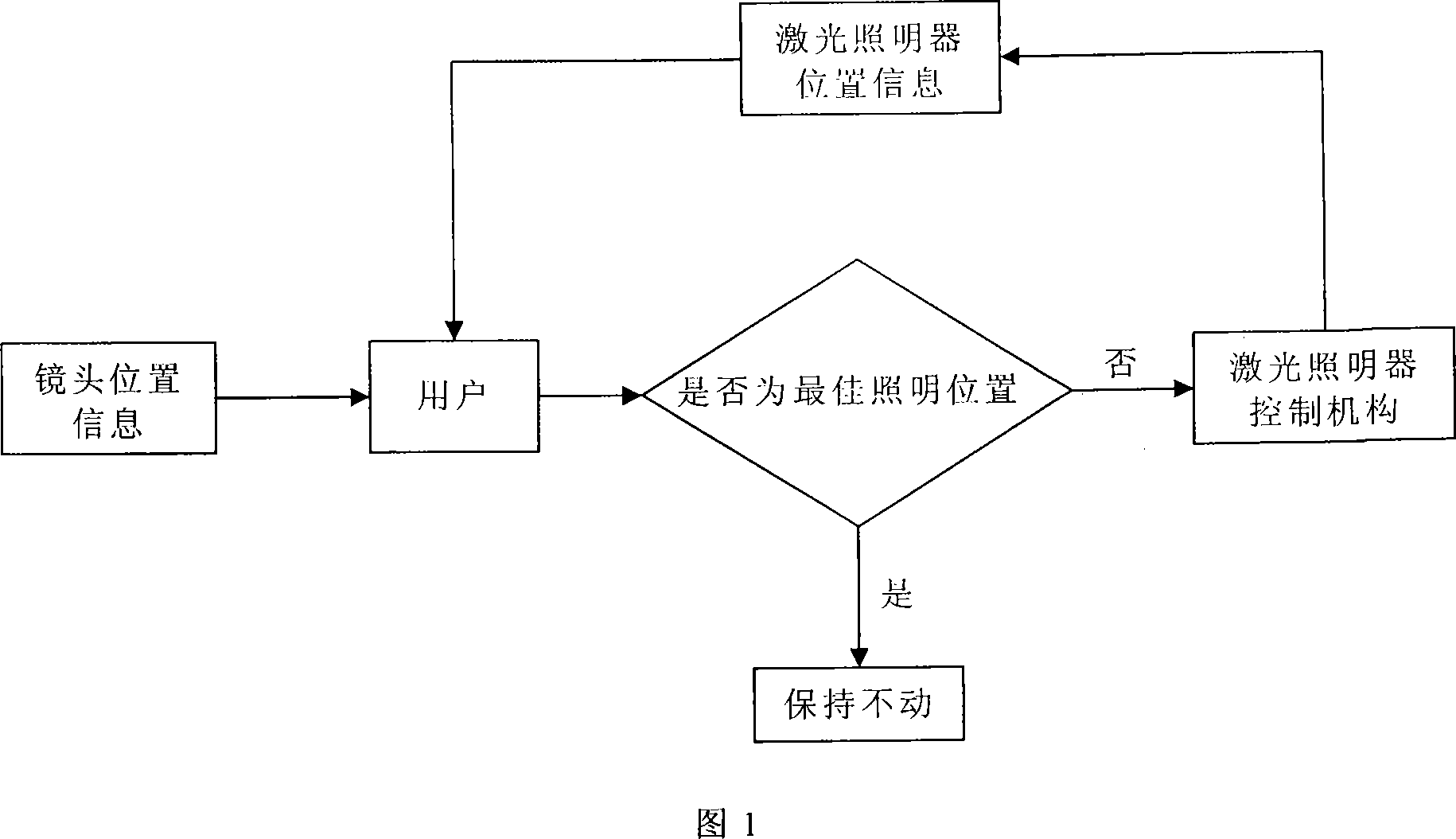
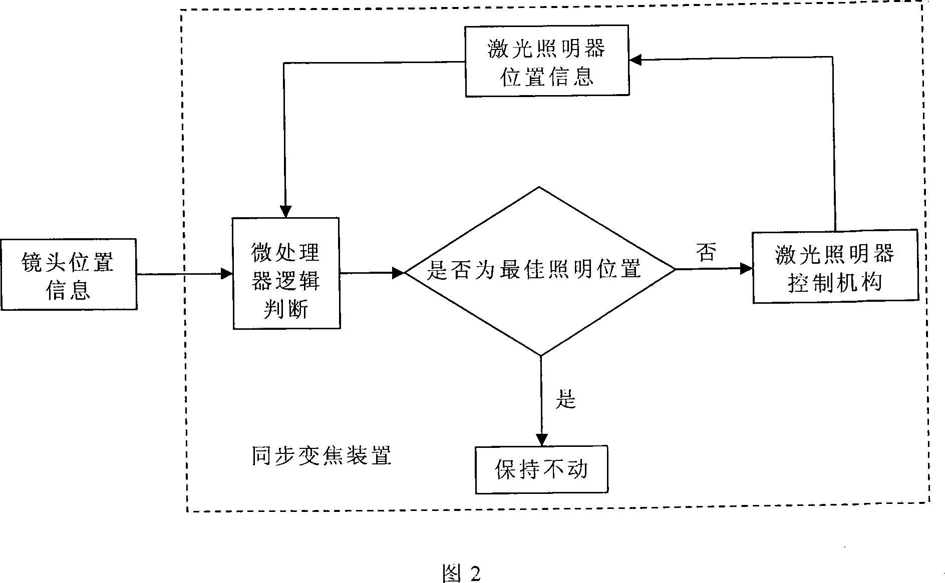
[0025] Figure 1 is a schematic diagram of independent zoom control, and the independent zoom control system is a control system in which humans are the main controller. The operator observes the lens zoom position information and the laser illuminator zoom position information to judge whether the laser illuminator is in the best lighting effect now. If the laser illuminator is in the best lighting zoom position now, keep the current zoom position still, otherwise The operator controls the laser control mechanism to achieve the best lighting effect.

[0026] Since human observation is closest to the actual use effect, the lighting effect of this operating system is the best. However, the independent control system must be controlled by humans. Once the lens zoom position information changes, the operator must adjust the laser zoom position in real time. The dependence on human makes this system unable to operate without human, and it is difficult to realize real-time automati...


PUM


Abstract

A synchronous verifocus device of laser illuminator is prepared for forming intelligent circuit control unit by microprocessor, A / D conversion chip and output driving chip; using mechanical driving mechanism to vary illumination angle of laser illuminator and to provide feedback signal for circuit control unit.

Description

(1) Technical field [0001] The invention relates to a laser illuminator, in particular to a synchronous zoom device of the laser illuminator, especially an application device when the laser is used as a zoom illumination light source. (2) Background technology [0002] With the development of laser lighting night vision technology, electric zoom laser illuminators with variable lighting angles have appeared. The patent application title invented by the applicant is "long-distance and large-range semiconductor laser illuminator zoom device". The patent application number is 20062008456.1. The utility model patent can adjust the laser lighting angle in a large range, and adopts an electric control method, which has strong versatility. It can be easily combined with the existing security control equipment, and the operator can independently control the illumination angle of the zoom laser illuminator at the background control terminal to make it consistent with the field of vie...

Claims


Application Information

Patent Timeline
Patent Type & Authority Applications(China)
IPC IPC(8): F21K7/00G05B19/04H05B37/02F21K99/00F21V14/00G02B15/16
Inventor 夏立民田忠超赵万存桑建国赵敬伟陈大明
Owner 山东神戎电子股份有限公司
Why Eureka
Try Eureka