Electric appliance circuit control switch and controlable door

A technology for circuit control and electrical appliances, applied in the field of remote control switches, can solve the problems of damage to infrared receivers and processing modules, easy breakdown of high-voltage signals, etc., and achieve the effects of simple structure, convenient control and accurate transmission

Inactive Publication Date: 2007-10-10
王光树
View PDF0 Cites 3 Cited by
  • Summary
  • Abstract
  • Description
  • Claims
  • Application Information

AI Technical Summary

Problems solved by technology

Although the control switch makes it unnecessary for the user to manually control on or off the electrical appliances or circuits, since many existing electrical circuits are equipped with high-voltage devices, high-temperature devices or low-temperature devic...

Method used


Image

  • Electric appliance circuit control switch and controlable door
  • Electric appliance circuit control switch and controlable door
  • Electric appliance circuit control switch and controlable door

Examples


Embodiment Construction

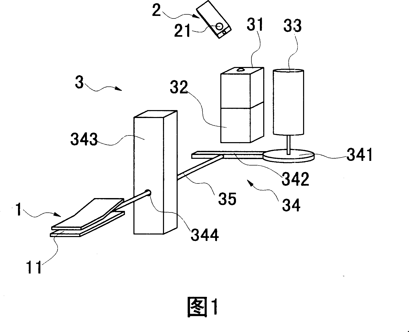
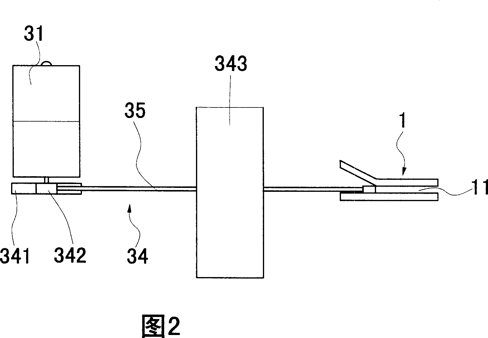
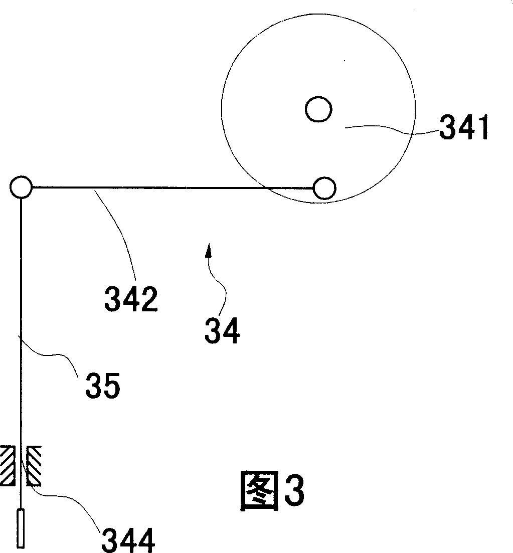
[0039] An electrical circuit control switch, as shown in Figures 1 and 2, is provided with a pair of connecting terminals 1 on the electrical appliance or circuit, which includes an infrared signal transmitter 2 and a control body 3; the infrared signal transmitter 2 is provided with a switch button 21; The control body 3 is provided with an infrared signal receiver 31 , a processing module 32 , a motor 33 , a mechanical transmission assembly 34 and a control member 35 .

[0040] The connecting terminal 1 is a conductive sheet, and there is an insulating gap 11 between the pair of connecting terminals 1 , and the conductive connection between the pair of connecting terminals 1 is insulated through the insulating gap. Wherein, the rear portion of the upper conductive sheet is turned upwards, which is convenient for the insertion of the control member 35 .

[0041] The upper surface of the infrared signal transmitter 2 is provided with a switch button 21. After the user presses ...


PUM

PropertyMeasurementUnit
Maximum rotation angleaaaaaaaaaa

Abstract

The control procedure of control switch includes steps: user pushes switch button, and the emitter transmits command signal for switch; the receiver receives the command signal for switch, and transfers the signal to the process module; the process module processes the command signal for switch, and controls the switch of electromotor; through mechanical drive module, the electromotor drives movement of the control part; further, movement of the control part controls on/off between a pair of connecting terminals so as to control opening or closing door. In the disclosed technical scheme, the process module does not control on/off between a pair of connecting terminals directly, instead, controls on/off of electromotor. Thus, the receiver, the process module is separated off connecting terminals of circuit so that signals of voltage in circuit, or high/low temperature will not affect or damage the receiver or process module. The invention guarantees accuracy of control signal.

Description

Technical field [0001] The invention relates to an electrical circuit control switch, in particular to a remote control switch for an electrical circuit and a door controlled by the control switch. Background technique [0002] Early electrical circuit control switches are usually manual control switches, and the user directly controls the on or off of the electrical appliance or circuit manually, which is unsafe and inconvenient to use. In order to solve the above shortcomings, many people have proposed solutions. Among them, the Chinese patent database disclosed a solution named two-wire control multi-channel remote control power switch on October 29, 2003. The patent authorized The announcement number is 2583882Y. A two-wire multi-channel remote control power switch. The device has an infrared transmitter and an infrared receiver. Both the transmitter and the receiver only need to lay two power lines. The transmitter has a switch and a transmitter, and the receiver has a...

Claims


Application Information

Patent Timeline
IPC IPC(8): H01H3/26G08C23/04E05F15/10E05F15/603E05F15/70
Inventor 王光树
Owner 王光树
Why Eureka
Try Eureka