Step travel wave amplifier circuit

A traveling wave amplifier and circuit technology, which is applied to amplifiers, amplifiers with distributed constants in coupling networks, and parts of amplifier devices, etc. Self-excited oscillation of traveling wave amplifier, etc., to achieve the effect of increasing gain, broadening frequency band, and improving stability

Inactive Publication Date: 2007-10-10
BEIJING ZHONGKE XINWEITE SCI & TECH DEV
View PDF0 Cites 3 Cited by
  • Summary
  • Abstract
  • Description
  • Claims
  • Application Information

AI Technical Summary

Problems solved by technology

[0004] In order to overcome the problem that the gain of existing traveling wave amplifiers cannot be increased in direct proportion to the number of stages and the problem that the gain is difficult to increase and the problem that multi-stage cascaded traveling wave amplifiers are easy to self-excited oscillation, the present invention provides a ladder traveling wave amplifier circuit to solve the problem of The above problems also broaden the frequency band

Method used


Image

  • Step travel wave amplifier circuit
  • Step travel wave amplifier circuit
  • Step travel wave amplifier circuit

Examples


Embodiment Construction

[0016] The system of the present invention will now be described in further detail with reference to the accompanying drawings.

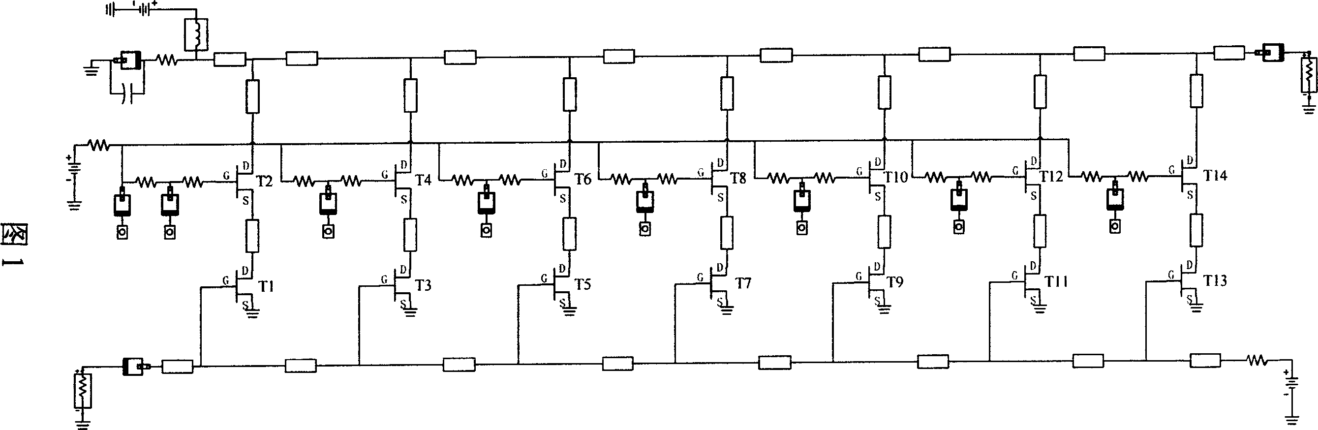
[0017] Figure 1 is a circuit diagram of a traditional traveling wave amplifier. Referring to Figure 1, T1, T2, T3...T14 in the figure represent 14 transistors respectively, of which T1 and T2, T3 and T4, T5 and T6, T7 and T8, T9 and T10, T11 and T12, and T13 and T14 respectively The 7-stage cascode structure, the 7-stage cascode structure is connected in series to form a traditional traveling wave amplifier structure as shown in FIG. 1.

[0018] When this traditional structure is connected in series within 3 to 4 stages of transistors, the average gain per stage is relatively large. But if more than 5 stages are connected in series, the gain effect of each stage will decrease quickly, which is difficult to achieve

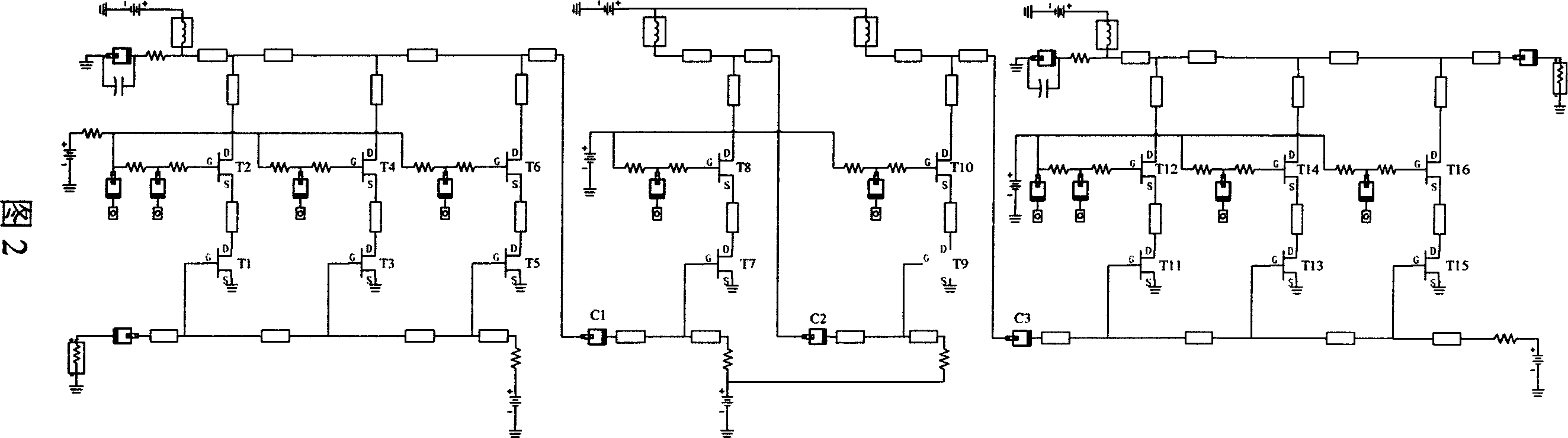
[0019] Therefore, the present invention adopts a stepped traveling wave amplifier circuit whose structure is shown in FIG. 2. The core idea...


PUM


Abstract

The disclosed traveling wave amplifier divides circuit of multistage traveling wave amplifier into multiple segments. Each segment includes 2 - 5 stage traveling wave amplification, and phase inversion amplification circuit (PIAC) connected between adjacent two segments. PIAC is bipolar transistor circuit or field effect transistor circuit in 1 - 2 stages. Capacitance is connected between each segment and PIAC. The invention increases gain of traveling wave amplifier obviously, widens frequency band, and raises stability of circuit.

Description

Technical field [0001] The invention relates to a traveling wave amplifier circuit for ultra-wideband amplification, in particular to a stepped traveling wave amplifier circuit connected in series with an inverting amplifier circuit. Background technique [0002] At present, the ultra-wideband amplifier circuits on the market are mostly implemented by traveling wave amplifier circuits, and this method has a very wide range of applications in communication equipment. The typical circuit topology of this traveling wave amplifier is shown in Figure 1. Referring to Figure 1, the circuit is composed of multiple stages of amplification to achieve gain, but in fact the gain of each stage is not high, about 1.5-2dB. Therefore, in order to obtain a sufficiently high gain, the number of amplification stages must be increased, usually as many as 7-9 stages, to achieve a gain of 14-15dB. However, when the number of stages increases to a certain value, the gain cannot increase in proportion t...

Claims


Application Information

Patent Timeline
IPC IPC(8): H03F1/18H03F3/60
Inventor 刘训春黄清华郝明丽
Owner BEIJING ZHONGKE XINWEITE SCI & TECH DEV
Why Eureka
Try Eureka