GOS ceramic scintillating fiber optics X-ray imaging plate for use in medical DF and RF imaging and in CT

A technology for scintillating fibers and ceramics, used in the use of radiation for material analysis, X/γ/cosmic radiation measurements, scientific instruments, etc.

Inactive Publication Date: 2007-10-10
KONINKLIJKE PHILIPS ELECTRONICS NV
View PDF0 Cites 13 Cited by
  • Summary
  • Abstract
  • Description
  • Claims
  • Application Information

AI Technical Summary

Problems solved by technology

[0005] The main disadvantage of...

Method used


Image

  • GOS ceramic scintillating fiber optics X-ray imaging plate for use in medical DF and RF imaging and in CT
  • GOS ceramic scintillating fiber optics X-ray imaging plate for use in medical DF and RF imaging and in CT
  • GOS ceramic scintillating fiber optics X-ray imaging plate for use in medical DF and RF imaging and in CT

Examples


Embodiment Construction

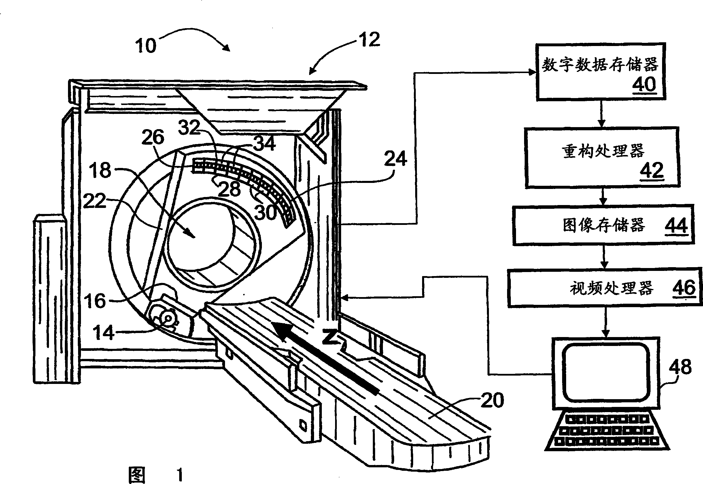
[0026] Referring to FIG. 1 , a computed tomography (CT) imaging apparatus or CT scanner 10 includes a gantry 12 . The x-ray source 14 and source collimator 16 cooperate to produce a fan, cone, wedge, or other shaped x-ray beam that is directed into an examination region 18 containing an object (not shown) disposed on an object support 20. shown), such as patients. The subject support 20 is linearly movable in the Z direction, while the x-ray source 14 on the rotating gantry 22 rotates about the Z axis.

[0027] Preferably, the rotating gantry 22 rotates simultaneously with the linear advancement of the subject support 20 to create a generally helical trajectory of the x-ray source 14 and collimator 16 around the examination region 18 . However, other imaging modalities may also be employed, such as single-slice or multi-slice imaging modalities in which the gantry 22 is rotated while the subject support 20 is held stationary to produce a generally circular trajectory of the x...


PUM

PropertyMeasurementUnit
Thicknessaaaaaaaaaa

Abstract

A radiation detector (24) for an imaging system includes a two-dimensional array (50) of nondeliquescent ceramic scintillating fibers or sheets (52). The scintillating fibers (52) are manufactured from a GOS ceramic material. Each scintillating fiber (52) has a width (d2) between 0.1 mm and I mm, a length (h2) between 0.1 mm and 2mm and a height (h8) between 1mm and 2mm. Such scintillating fiber (52) has a height (h8) to cross-sectional dimension (d2, h2) ratio of approximately 10 to 1. The scintillating fibers (52) are held together by layers (86, 96) of a low index coating material. A two-dimensional array (32) of photodiodes (34) is positioned adjacent and in optical communication with the scintillating fibers (52) to convert the visible light into electrical signals. A grid (28) is disposed by the scintillating array (50). The grid (28) has the apertures (30) which correspond to a cross-section of the photodiodes (34) and determine a spatial resolution of the imaging system.

Description

technical field [0001] This application involves the use of large imaging plates. The subject matter of the present application finds particular use and is described with particular reference to computed tomography (CT) scanners. However, the present invention finds use in combining DF and RF imaging, x-ray fluoroscopy, radiography, and other inspection systems for medical and non-medical inspections. Background technique [0002] Computed tomography (CT) imaging generally employs an x-ray source that produces a fan beam, wedge beam, or cone beam of x-rays that traverse the examination region. Objects arranged in the examination region interact with and absorb parts of the traversing x-rays. A two-dimensional radiation detector comprising an array of detector elements is positioned opposite the x-ray source to detect and measure the intensity of emitted x-rays. [0003] Typically, the x-ray source and radiation detectors are mounted on opposite sides of a rotating gantry ...

Claims


Application Information

Patent Timeline
IPC IPC(8): G01T1/24G01T1/20G01N23/02G01T1/22G01N23/04G01T1/00
CPCG01T1/201G01T1/2985
Inventor S·利维恩R·A·马特森A·阿尔特曼
Owner KONINKLIJKE PHILIPS ELECTRONICS NV
Why Eureka
Try Eureka