Flat vibration motor

A flat vibrating motor and vibrating force technology, which is applied in the direction of electric components, manufacturing motor generators, casings/covers/supports, etc., can solve the problem of complex manufacturing and assembly processes of flat vibrating motors, inability to maintain sufficient pressure, and reduced elasticity and other problems to achieve the effect of preventing swing or deformation, increasing output and preventing deformation

Inactive Publication Date: 2010-09-15
LG INNOTEK CO LTD +1
View PDF0 Cites 0 Cited by
  • Summary
  • Abstract
  • Description
  • Claims
  • Application Information

AI Technical Summary

Problems solved by technology

In this case, during the manufacture of the product, assembly defects may occur
[0023] In addition, when the terminal 50 cannot withstand a certain amount of pressure and is deformed in the direction of the open side of the base, its elasticity is reduced, so that a sufficient pressure for contacting the external terminal cannot be maintained.
[0024] In addition, the flat vibration motor manufacturing and assembly process according to the related art is somewhat complicated

Method used


Image

  • Flat vibration motor
  • Flat vibration motor
  • Flat vibration motor

Examples


no. 1 approach

[0064] A detailed description will now be given of a flat vibration motor according to a first embodiment of the present invention with reference to the accompanying drawings.

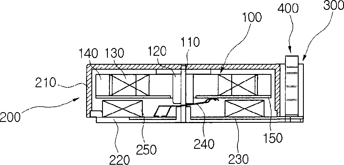
[0065] Figure 4 is an exploded perspective view showing how the base portion 300, the terminal 400, and the stator portion 200 of the flat vibration motor according to the first embodiment of the present invention are assembled.

[0066] refer to Figure 4 , a fixing bracket 260 for supporting the base part 300 is formed at a side of the lower case 220 of the stator part 200 .

[0067] The fixing bracket 260 is a rectangular plate, and the second circuit board 230 is disposed on its top surface.

[0068] The terminal 400 includes a contact portion 410 , an elastic portion 420 and an engaging portion 430 . In the first embodiment of the present invention, two terminals 400 are provided, and the two terminals are arranged symmetrically opposite to each other on the second circuit board 230 . However...

no. 2 approach

[0094] A detailed description will be given below of a joint structure of the base part 300', the terminal 400', and the stator part 200' according to the second embodiment of the present invention with reference to the accompanying drawings.

[0095] Figure 7 is an exploded perspective view showing how the base part 300', the terminal 400' and the stator part 200' of the flat vibration motor according to the second embodiment of the present invention are assembled; Figure 8 is a perspective view showing a base portion 300' coupled with a terminal 400' of a flat vibration motor according to a second embodiment of the present invention.

[0096] refer to Figure 7 with 8 , the stator part 200' is formed with a fixing bracket 260 protruding from the lower case of the stator part 200'. The fixing bracket 260 is a rectangular plate, and has the second circuit board 230 fixed thereon.

[0097] The terminal 400' includes a contact portion 410, an elastic portion 420 and an eng...

no. 3 approach

[0117] Figure 9 is an exploded perspective view showing how the base part 300", the terminal 400", and the stator part 200 of the flat vibration motor according to the third embodiment of the present invention are assembled.

[0118] refer to Figure 9 , in the stator part 200 including the upper case 210 and the lower case 220, the lower case 220 has a fixed bracket 260 formed on its side, where the fixed bracket 260 is a rectangular plate supporting the bottom of the base part 300" and There is a second circuit board 230 thereon.

[0119] The terminal 400 ″ of the flat vibration motor according to the third embodiment includes a contact part 410 , an elastic part 420 ″ and an engaging part 430 ″, and is disposed on the fixing bracket 260 to be opposed to each other.

[0120] Two terminals 400" are provided in the third embodiment, but other numbers may be provided.

[0121] The joint part 430" may be connected to a part of the second circuit board 230 by soldering, and t...


PUM


Abstract

A flat vibration motor is provided. The flat vibration motor includes a rotor portion, a stator portion, a fixing mount, a pair of terminals, and a base portion. The rotor portion generates vibrating force when rotating. The stator portion houses and couples with the rotor portion to allow the rotor portion to rotate. The fixing mount extends from a side of a lower case of the stator portion. Each terminal includes a contacting portion, an elastic portion, and a joining portion. The base portion forms a plurality of supporting holes through which each of the terminals respectively passes. Thejoining portion of the terminal connects electrically to the circuit board through a peripheral lower surface around the supporting hole, when the base portion and the fixing mount are coupled.

Description

technical field [0001] The invention relates to a vibration motor, in particular to a flat vibration motor. Background technique [0002] The flat vibrating motor is a miniature motor that can be installed in cellular phones, smart phones, personal digital assistants (PDAs) and similar mobile communication terminals, as well as various other electronic devices. When a signal is received from a call center, the flat vibrating motor notifies the user of an incoming call by vibrating instead of sound. [0003] More specifically, when set in the "polite mode", the mobile communication terminal vibrates through the operation of such a flat vibration motor. [0004] The flat vibrating motor is coin-sized and generates a strong vibrating force, so it requires a relatively durable connection structure. However, its terminals are often deformed due to strong vibration force, so the contact point is changed. [0005] figure 1 is a perspective view of a flat vibration motor accordi...

Claims


Application Information

Patent Timeline
Patent Type & Authority Patents(China)
IPC IPC(8): H02K5/22
CPCH02K5/225H02K7/065H02K15/03H02K15/14
Inventor 文炳熙严在晙
Owner LG INNOTEK CO LTD
Why Eureka
Try Eureka