Axial magnetic bearing for magnetic levitation flywheel

A technology of axial magnetic bearing and magnetic levitation, which is applied in the direction of shafts and bearings, bearings, engine components, etc., can solve the problems of high power consumption, difficulty in accurate compensation, unfavorable high-precision control of magnetic levitation flywheels, etc., to reduce power consumption and The effect of small axial size, low axial translational comprehensive stiffness and radial torsional comprehensive stiffness

Inactive Publication Date: 2007-10-17
BEIHANG UNIV
View PDF1 Cites 28 Cited by
  • Summary
  • Abstract
  • Description
  • Claims
  • Application Information

AI Technical Summary

Problems solved by technology

In addition, whether it is an electromagnetic biased magnetic bearing or a permanent magnetic biased magnetic bearing, its large displacement negative stiffness due to bias will affect the high-precision control of the magnetic levitation flywheel. This is because the main function of the magnetic levitation flywheel is through the acceleration of the flywheel motor. and deceleration output torque to adjust the attitude of satellites and other spacecraft equipped with magnetic levitation flywheels. In order to prevent them from generating disturbance torque to the stars, it is necessary to make the magnetic levitation flywheel rotor rotate around its inertial axis to eliminate the same-frequency disturbance caused by rotor imbalance. The displacement negative stiffness generated by the bias magnetic field of the electromagnetic bias or permanent magnetic bias magnetic bearing will generate a disturbance torque when the rotor has a small offset, and accurate compensation is very difficult, which is unfavorable for the high-precision control of the magnetic levitation flywheel. In short, Existing axial magnetic bearings have the disadvantages of high power consumption, inability to control radial torsion, and difficulties in meeting the requirements of magnetic levitation flywheels for axial length and high-precision control

Method used


Image

  • Axial magnetic bearing for magnetic levitation flywheel
  • Axial magnetic bearing for magnetic levitation flywheel
  • Axial magnetic bearing for magnetic levitation flywheel

Examples


Embodiment Construction

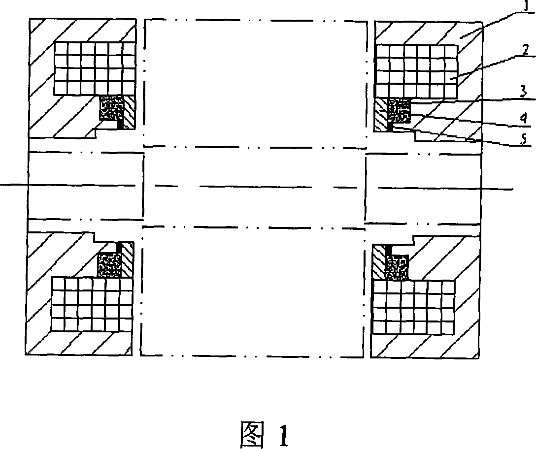
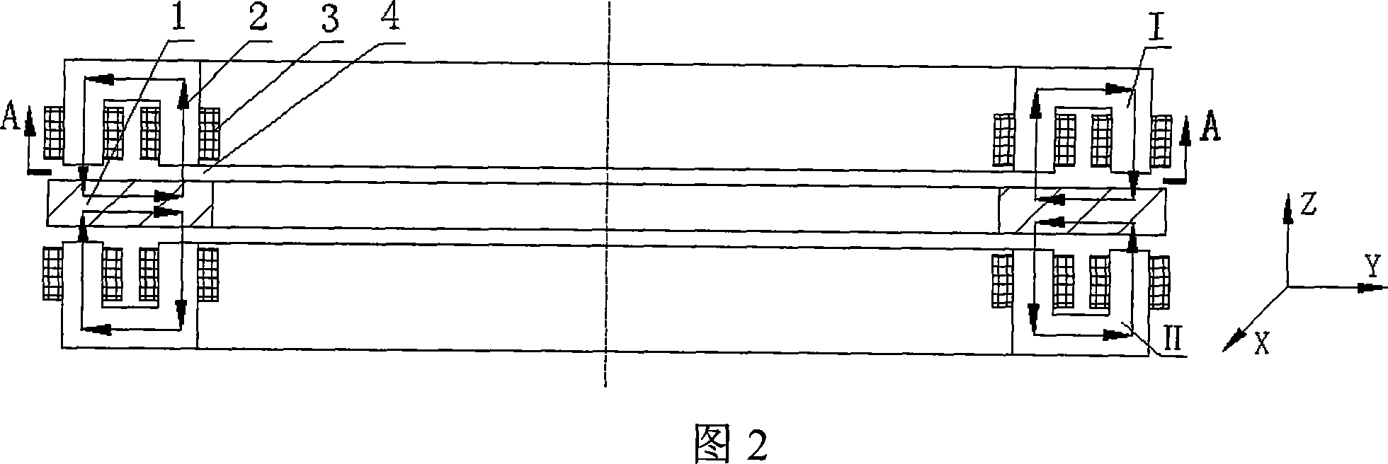
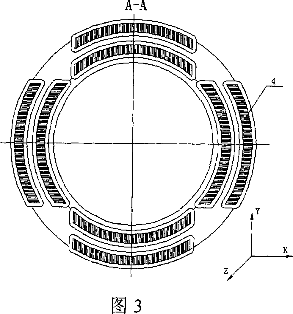
[0012] As shown in Fig. 2 and Fig. 3, the present invention is made up of stator part and rotor 1, and stator part is made up of 4 stator cores 2 and coil 3, and 4 stator cores 2 constitute 8 stator core magnetic poles on the whole circumferential direction, and Placed along the +X, -X, +Y, -Y directions, in order to increase the cross-sectional area of ​​the stator core magnetic pole to improve the bearing capacity of the axial magnetic bearing, the area of ​​the stator core magnetic pole is made into an arc surface. A coil 3 is wound on each stator core pole, and an axial magnetic air gap 4 is formed between the stator part and the rotor. The axial magnetic air gap 4 formed by the stator core 2 and the rotor part 1 is 0.2-0.4 mm. In order to realize the control of axial translation and radial torsion, the axial magnetic bearings of the present invention need to be used in pairs, which are respectively defined as I and II. When installing, ensure that the magnetic poles of th...


PUM


Abstract

An axial magnetic bearing for magnetic suspension flywheel is composed of a stator and a rotor, the stator is composed of four group of stator cores, and windings, the four group of stator cores compose eight stator poles on circumference direction and are put along +X, -X, +Y, -Y direction, each stator core pole is winded with a winding. An axial magnetic gas gap is formed between the stator and the rotor. The invention can realize the axial movement and radial twist control for the magnetic suspension rotor by the four group of stator cores distributed in +X, -X, +Y, -Y direction, and can greatly reduce the axial size of the system. The axial magnetic bearing also has the advantages of non-biased, low power consume and reliable property.

Description

technical field [0001] The invention relates to a non-contact magnetic suspension bearing, in particular to an axial magnetic bearing for a magnetic suspension flywheel. Background technique [0002] Commonly used magnetic suspension bearings are divided into electromagnetic bias type and permanent magnetic bias plus electromagnetic control hybrid magnetic suspension bearing. The former uses current to generate a bias magnetic field, so the working current is large and the power consumption is large. The latter uses permanent magnets instead of current to generate a bias magnetic field. , The magnetic field generated by the permanent magnet bears the main bearing capacity, and the electromagnetic field provides the auxiliary adjustment bearing capacity, so this kind of bearing can greatly reduce the control current and reduce the loss. However, in the existing permanent magnet bias axial magnetic bearing, its electromagnetic circuit passes through the permanent magnet, so it...

Claims


Application Information

Patent Timeline
IPC IPC(8): F16C32/04
CPCF16C32/0485F16C2361/55
Inventor 房建成孙津济刘虎刘刚王曦杨磊
Owner BEIHANG UNIV
Why Eureka
Try Eureka