Movable flange self-balanced flexible connection tube

A flexible nozzle, balanced technology, applied in the direction of pipe/pipe joint/pipe fitting, adjustable connection, passing element, etc., can solve the problems of small axial displacement compensation ability, poor balance, difficult alignment of manufacturing errors, etc. Improve vibration isolation and noise reduction, reduce vibration and noise transmission, reduce installation workload and labor intensity

Inactive Publication Date: 2007-10-17
704TH RES INST OF CHINA SHIPBUILDING IND CORP
View PDF0 Cites 1 Cited by
  • Summary
  • Abstract
  • Description
  • Claims
  • Application Information

AI Technical Summary

Problems solved by technology

[0002] In mechanical equipment, the harmfulness of vibration and noise is well known. Due to the use of various vibration isolation technologies on the installation base, the transmission of vibration and noise has been significantly controlled. Therefore, the vibration transmitted through the "second channel" of the pipeline The noise problem has aroused people's attention. In order to reduce the vibration and noise of the pipeline, the technical scheme of installing flexible pipe joints is generally adopted, which has obvious technical effects. However, these flexible pipe fittings will produce axial deformation, which will give the connected The pipeline or equipment brings additional force and displacement. When the force and displacement are too large, it will affect the normal operation of the system or bring serious consequences. The axial displacement and corresponding reaction force generated when the above-mentioned pipeline flexibly takes over the load , is the main evaluation index of the balance of flexible joints; in important pipeline systems, flexible joints with excellent balance are required, and a reinforced rubber hose with built-in fastener joints was used in the early days. The balance of this structure is poor, its size, weight and rigidity are too large, the axial displacement compensation ability is small, and the vibration reduction effect is not ideal; for this reason, the industry has proposed technical solutions such as balanced rubber vibration-damping joints and balanced metal bellows , which is characterized by the use of an external limit structure to solve the balance problem. It has been proved that its balance effect is not good. The limit structure will have a large limit on the axial displacement compensation, and it is difficult to adapt to the vibration reduction and balance of important pipeline systems. Strict requirements; on the basis of the above, the Chinese patent name is the three-flange structure self-balancing flexible joint (patent number ZL20042001702.3) proposed another improved technical solution, the connection end of the hose body of the solution has three flanges , there is a spacer sleeve in the three flanges, a fiber skeleton layer in the pipe body, and the skeleton layer is clamped by the three flanges. Compared with the existing technical scheme, the three-flange structure can ensure the anti-pull-off ability of the joint and increase the strength of the pipe body. The relative length of the flexible section improves the vibration reduction and displacement compensation capabilities, and makes the pipe fittings have better balance under the action of working pressure (small deformation, small balance reaction force) with a better fiber winding angle, but the solution still has the following question:
[0003] 1. Inconvenient installation: Since the fixed flange and the fixed connection of the pipe body with skeleton are inseparable, when the three flanges of the flexible pipe connect with the rigid pipe flange in the pipe system, it is difficult to align the fixed holes at both ends due to manufacturing errors , at the same time, a sealing ring must be set between the joint surface of the flexible pipe flange and the rigid pipe flange to maintain the sealing of the pipeline, thus causing trouble for the overall installation operation;
[0004] 2. Due to the positioning error of each fixing hole between the two flanges at the joint, the flexible joint may only be docked and fixed with the rigid pipe under the state of a slight twist in the circumferential direction, thus affecting the best winding of the fiber skeleton layer in the rubber hose The angle reduces the balance of the flexible joint and even affects the performance of the overall piping system;

Method used


Image

  • Movable flange self-balanced flexible connection tube
  • Movable flange self-balanced flexible connection tube
  • Movable flange self-balanced flexible connection tube

Examples


Embodiment Construction

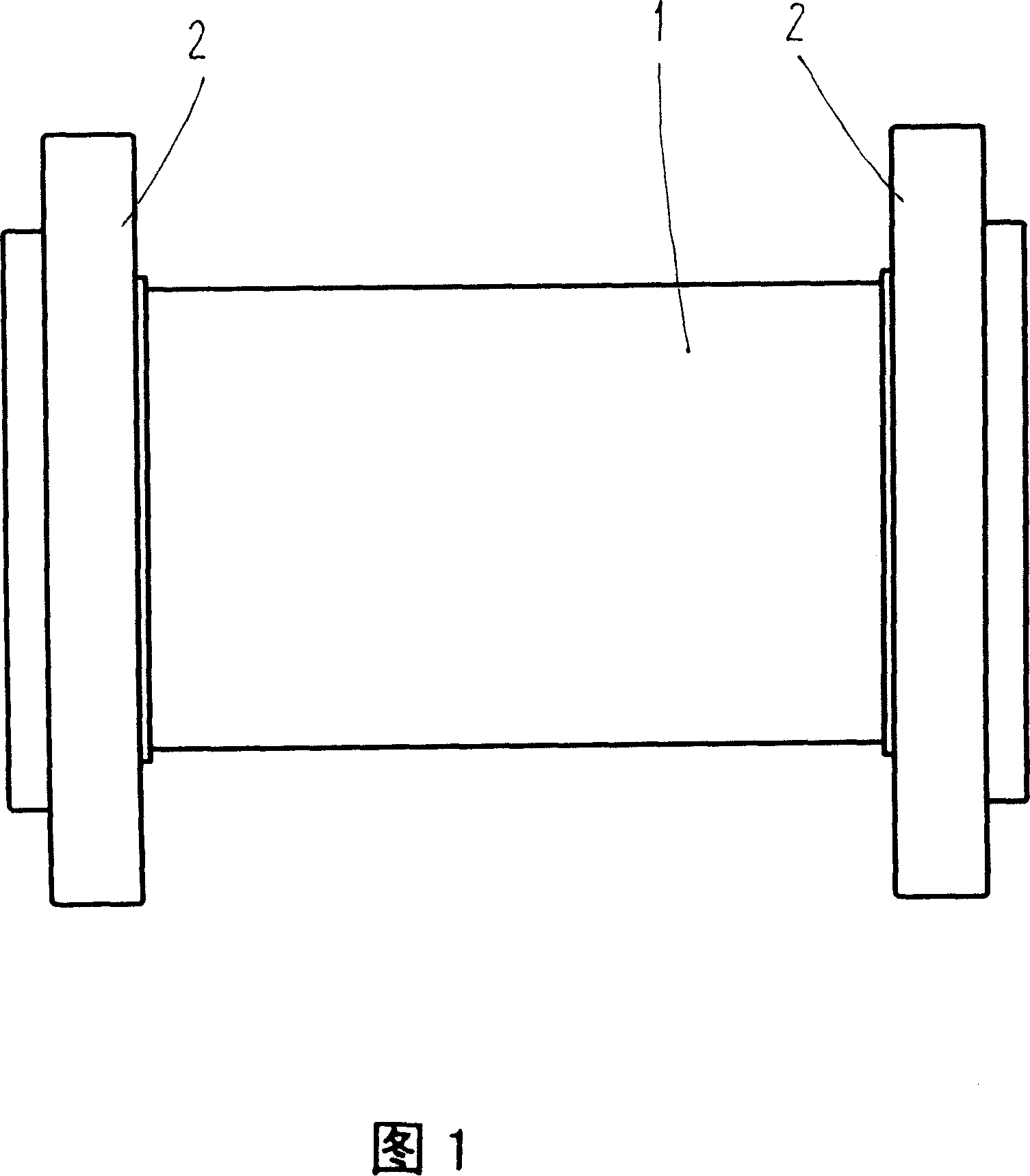
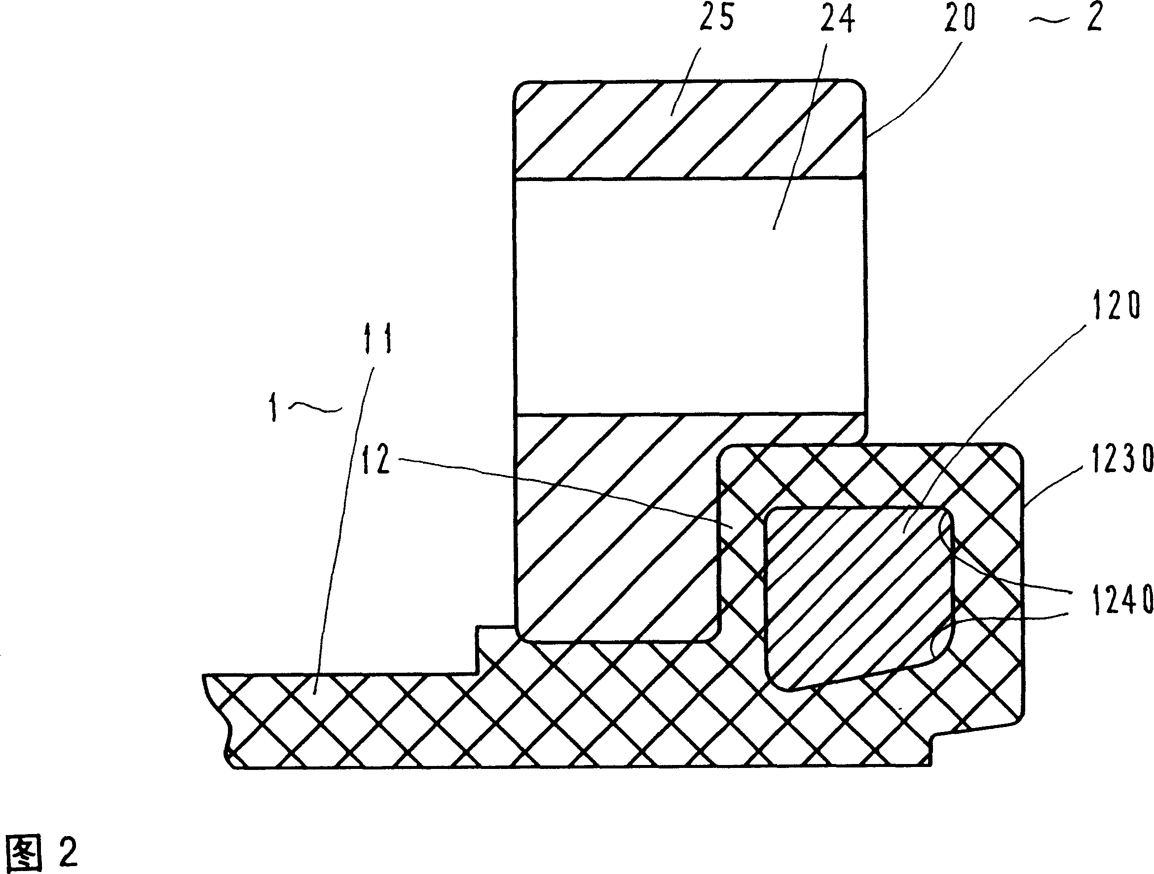
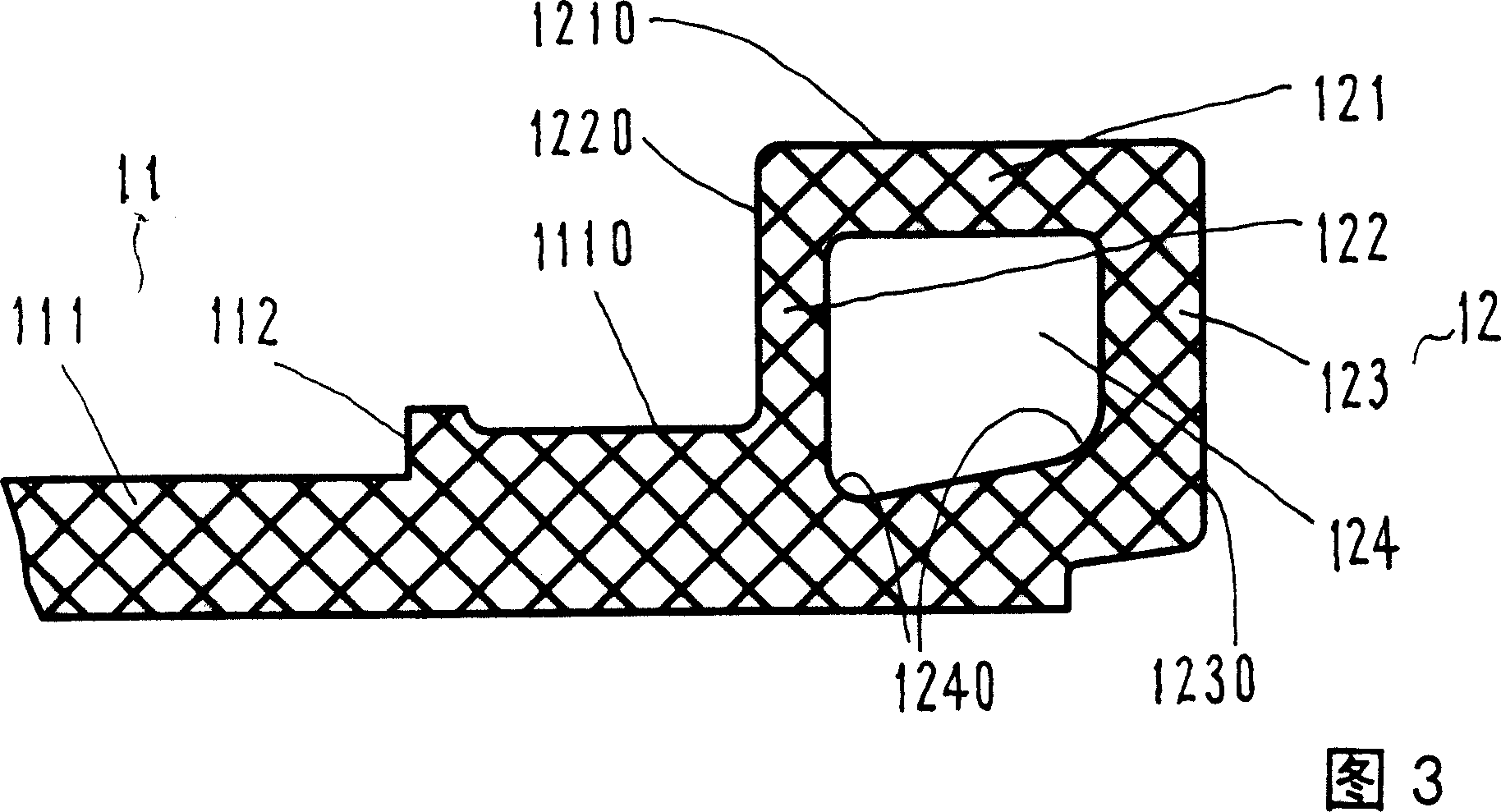
[0012] Referring to Figures 1 and 2, the active flange self-balancing flexible joint includes a hose 1 and a flange 2.

[0013] Rubber hose 1 is integrally formed by rubber and reinforcing materials. The inner rubber and flange joints are 50% natural rubber and 50% neoprene, and the outer layer is neoprene. The reinforcing material can be aramid fiber or For the steel wire, the winding angle of the fiber is determined by analyzing the best nozzle balance, fiber strength and nozzle stiffness. The pipe body 11 and the connection end 12 of the rubber hose 1 are integrated, and a flange 2 is respectively arranged on the two connection ends 12, forming the present invention. A unique loop-type flange structure, and advanced vulcanization process and corresponding molds can be used to ensure the elasticity and strength of the vulcanized rubber, the inner ring of the joint and the sealing rubber;

[0014] The cylinder body 111 of the pipe body 11 and the outer cylindrical surface 111...


PUM


Abstract

A loose flange self balancing flexible connection pipe mainly solves the technology problem of improving property and simplifying operation. The technical project is that: the two ends of the pipe body of a rubber pipe are respectively integrated with a flanged connection end, the connection end is disposed with a rigid ring, the two connection ends of the rubber pipe are respectively enclosed with a connecting flange, the connection ends of the rubber pipe are slip fitted with the connecting flanges, the two flanges are positioned in the inner side of the connection ends in axial direction. Then a flexible connection pipe with thin wall, low rigidity and high pressure can be formed, and can be adapted to various pipes with middle and small diameters.

Description

Technical field: [0001] The invention relates to an adjustable connection of pipe fittings, especially a connection including flexibility. Background technique: [0002] In mechanical equipment, the harmfulness of vibration and noise is well known. Due to the use of various vibration isolation technologies on the installation base, the transmission of vibration and noise has been significantly controlled. Therefore, the vibration transmitted through the "second channel" of the pipeline The noise problem has aroused people's attention. In order to reduce the vibration and noise of the pipeline, the technical scheme of installing flexible pipe joints is generally adopted, which has obvious technical effects. However, these flexible pipe fittings will produce axial deformation, which will give the connected The pipeline or equipment brings additional force and displacement. When the force and displacement are too large, it will affect the normal operation of the system or bring...

Claims


Application Information

Patent Timeline
Patent Type & Authority Applications(China)
IPC IPC(8): F16L27/10
Inventor 周相荣王强汪玉周强
Owner 704TH RES INST OF CHINA SHIPBUILDING IND CORP
Why Eureka
Try Eureka