Heat pipe

A technology for heat pipes and adiabatic sections, applied to heat pipes. It can solve problems such as small fluid return resistance and large capillary force that cannot be taken into account at the same time, and achieve the effects of increasing anti-gravity characteristics, reducing return resistance, and accelerating boiling efficiency.

Inactive Publication Date: 2007-10-17
FU ZHUN PRECISION IND SHENZHEN +1
View PDF0 Cites 8 Cited by
  • Summary
  • Abstract
  • Description
  • Claims
  • Application Information

AI Technical Summary

Problems solved by technology

[0006] The inside of the heat pipe adopts a single type of capillary structure from the evaporation section 40 to the condensation section 60, such as a single groove structure, a single sintered powder structure or a single screen structure, so that each part of the heat pipe can withstand The maximum heat flux density is almost the same. The single capillary structure of this structure cannot take into account the small fluid return resistance and the large capillary force at the same time, and it cannot provide an effective heat conduction path between the external heat source and the working liquid in the tube at the same time.

Method used


Image

  • Heat pipe
  • Heat pipe
  • Heat pipe

Examples


Embodiment Construction

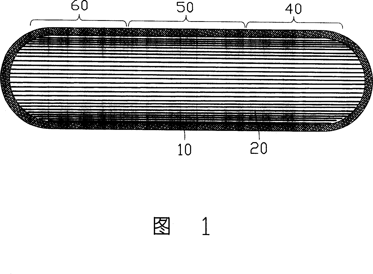
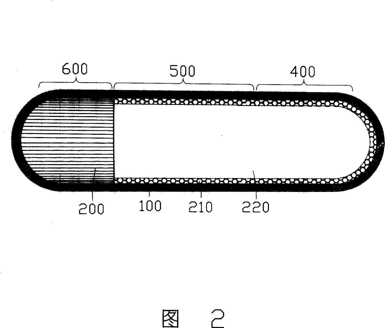
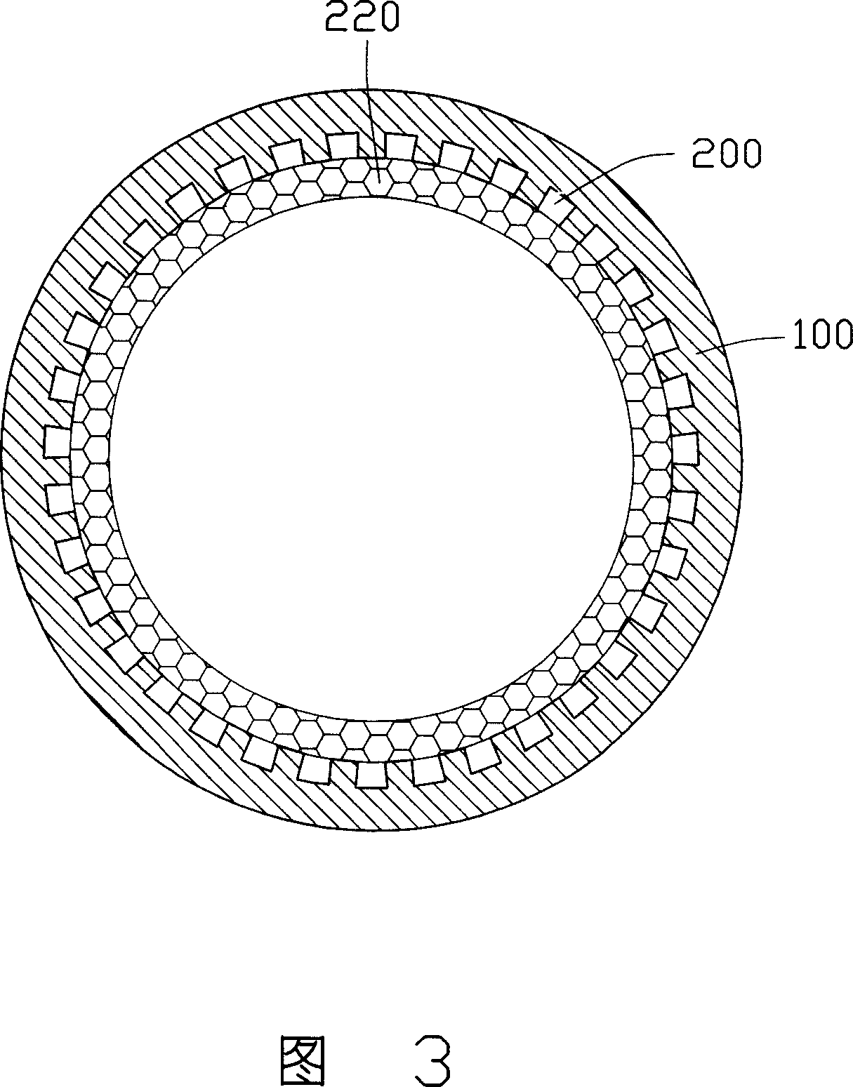
[0016] Fig. 2 and Fig. 3 are respectively the axial section of the first embodiment of the heat pipe of the present invention and the cross-sectional schematic diagram of the heat insulating section 500 thereof. The heat pipe is an example of a straight heat pipe, which mainly includes a housing 100 , a capillary structure disposed on the inner wall of the housing 100 , and an appropriate amount of working fluid (not shown) sealed in the housing 100 . The casing 100 can be made of metal materials with good thermal conductivity such as copper and aluminum, and the inside thereof is generally evacuated into a vacuum or close to a vacuum to facilitate the evaporation of the working fluid when heated. The working liquid is generally a liquid with high latent heat such as water, alcohol, ammonia water and their mixtures.

[0017] According to the functions, the heat pipe is divided into three parts: an evaporation section 400 , an adiabatic section 500 , and a condensation section ...


PUM


Abstract

The invention discloses a heat pipe which includes a sealed heat transmission cavity whose inner wall is equipped with capillary structure and in which appropriate working liquid is sealed. The heat pipe includes evaporation section, condensation section, thermal insulation section, and a first capillary structure and a second capillary structure is arranged in sequence on the inner wall of the thermal insulation section shell along the direction from the shell to inner cavity center, and the pore aperture of the first capillary structure is larger than the same of the second capillary structure. Two capillary structures with different pore apertures are arranged in sequence on the inner wall of the heat pipe, in this manner, reflux resistance of the liquid can be reduced to guarantee that the evaporation section has enough working liquid, and also a lot of steam nucleating points can be provided for the evaporation section to accelerate boiling efficiency for the working medium, in the meantime, the composite capillary structure of the thermal insulation section can increase antigravity property of the heat pipe, thereby improving heat conduction efficiency for the heat pipe.

Description

【Technical field】 [0001] The invention relates to a heat transfer device, in particular to a heat pipe. 【Background technique】 [0002] The heat pipe has the characteristics of ultra-quiet, fast heat transfer, high thermal conductivity, light weight, small size, no moving parts, simple structure and multi-purpose, and the heat pipe can quickly transfer a large amount of heat energy under the condition that the temperature remains almost constant. widely used as superconductors. [0003] The basic structure of the heat pipe is that the inner wall of the closed tube is lined with a capillary structure layer that is easy to absorb the working fluid, while the central space is in a hollow state, and an amount equivalent to the total pore volume of the capillary structure layer is injected into the vacuumed closed tube. dynamic fluid. The heat pipe can be divided into an evaporation section, a condensation section, and an adiabatic section in between according to the relative p...

Claims


Application Information

Patent Timeline
Patent Type & Authority Applications(China)
IPC IPC(8): F28D15/04
CPCF28D15/046
Inventor 侯春树刘泰健何谦华孙至贤童兆年
Owner FU ZHUN PRECISION IND SHENZHEN
Why Eureka
Try Eureka