Solid electrolytic capacitor and manufacturing method of the same

A technology of solid electrolysis and manufacturing method, applied in the direction of solid electrolytic capacitors, electrolytic capacitors, capacitors, etc., can solve problems such as loss of installability

Inactive Publication Date: 2007-10-17
PANASONIC CORP
View PDF1 Cites 7 Cited by
  • Summary
  • Abstract
  • Description
  • Claims
  • Application Information

AI Technical Summary

Problems solved by technology

This will compromise the installability

Method used


Image

  • Solid electrolytic capacitor and manufacturing method of the same
  • Solid electrolytic capacitor and manufacturing method of the same
  • Solid electrolytic capacitor and manufacturing method of the same

Examples


Embodiment Construction

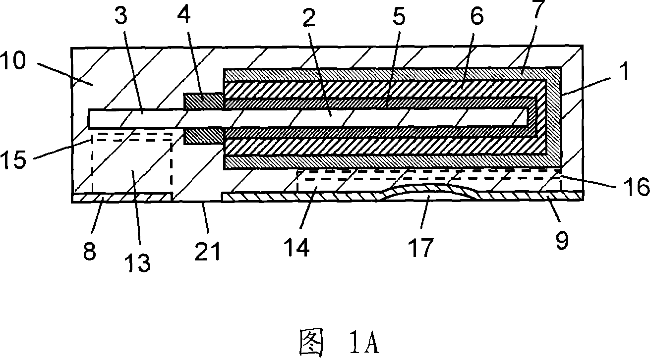
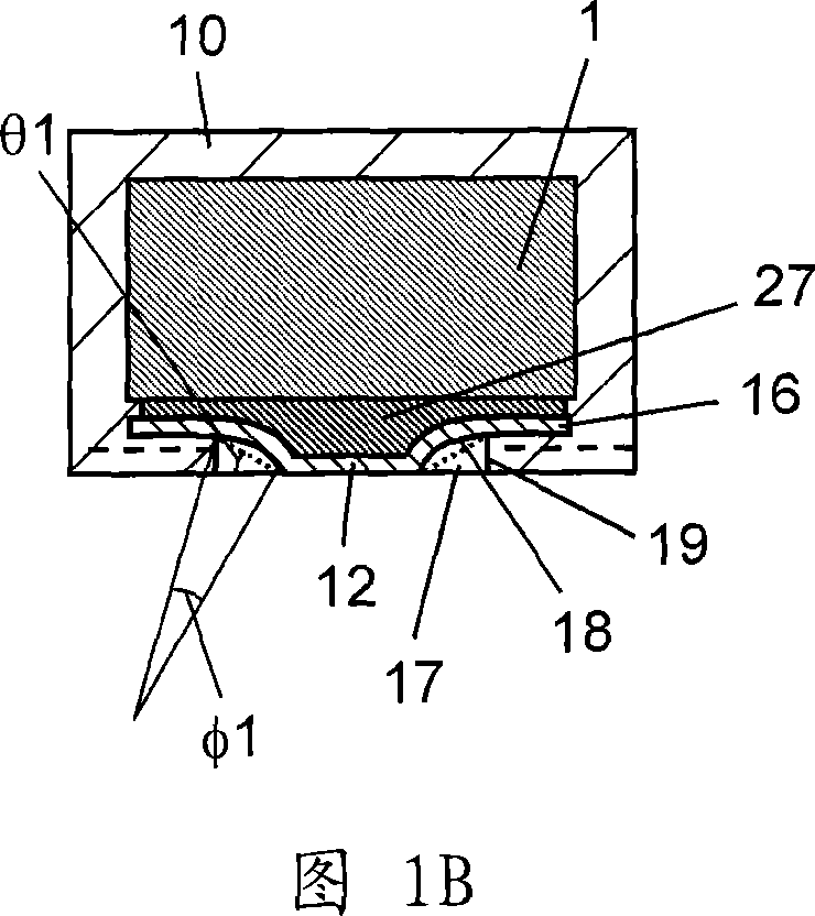
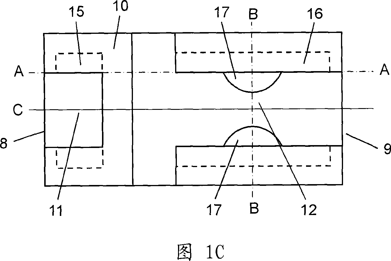
[0026] 1A is a side sectional view of a solid electrolytic capacitor according to an embodiment of the present invention, FIG. 1B is a front sectional view, and FIG. 1C is a bottom view. Wherein, FIG. 1A is a cross-sectional view along line A-A of FIG. 1C , and FIG. 1B is a cross-sectional view along line B-B of FIG. 1C .

[0027] The capacitor element 1 has an anode body 2 , an anode lead-out portion 3 , an insulator layer 4 , a dielectric oxide film 5 , a solid electrolyte 6 , and a cathode layer 7 . The anode body 2 is formed of a valve metal foil. The insulator layer 4 divides the anode body 2 into an anode part and a cathode part. The anode lead-out portion 3 is provided at one end of the anode portion of the anode body 2 , and the dielectric oxide film 5 is formed on the other end surface of the anode body 2 to be the cathode portion. A solid electrolyte 6 made of a conductive polymer is provided on the dielectric oxide film 5 . The cathode layer 7 is laminated on the...


PUM

PropertyMeasurementUnit
thicknessaaaaaaaaaa
particle sizeaaaaaaaaaa
thicknessaaaaaaaaaa

Abstract

A solid electrolytic capacitor includes a capacitor element, an anode terminal, a cathode terminal, and an outer casing resin. The anode and cathode terminals constitute parts of the mounting surface, and are drawn immediately below the capacitor element. The anode terminal and the cathode terminal are electrically coupled with an anode leader of the capacitor element and a cathode layer, respectively. The outer casing resin covers the capacitor element, and exposes the anode and cathode terminals on the mounting surface. At least one recess is provided on a mounting surface side of at least one of the anode and cathode terminals having a larger area projected onto the mounting surface.

Description

technical field [0001] The present invention relates to a solid electrolytic capacitor and a method of manufacturing the same. Background technique [0002] 7A to 7C show the configuration of a conventional solid electrolytic capacitor. 7A is a side sectional view, FIG. 7B is a front sectional view, and FIG. 7C is a bottom view. Wherein, FIG. 7A is a cross-sectional view along line A-A shown in FIG. 7C , and FIG. 7B is a cross-sectional view along line B-B shown in FIG. 7C . [0003] The capacitor element 61 has an anode body 62 , an anode lead-out portion 63 , a dielectric oxide film 64 , a solid electrolyte 65 , and a cathode layer 66 . Wherein, the anode body 62 is made of electron tube metal foil, the anode lead-out part 63 is provided at one end of the anode body 62 , and the dielectric oxide film 64 is provided on the surface of the other end of the anode body 62 . A solid electrolyte 65 made of a conductive polymer is provided on the dielectric oxide film 64 . The...

Claims


Application Information

Patent Timeline
Patent Type & Authority Applications(China)
IPC IPC(8): H01G9/15H01G9/012
CPCH01G9/10Y10T29/417H01G9/012H01G9/15
Inventor 中村克之川人一雄城土井贵博山口秀人
Owner PANASONIC CORP
Why Eureka
Try Eureka