Low-temperature plasma diagnosis device

A low-temperature plasma and diagnostic device technology, applied in the field of plasma diagnosis, can solve the problems of large plasma interference, large volume, and poor real-time measurement

Inactive Publication Date: 2007-10-17
NORTHEASTERN UNIV
View PDF0 Cites 23 Cited by
  • Summary
  • Abstract
  • Description
  • Claims
  • Application Information

AI Technical Summary

Problems solved by technology

At present, when the Langmuir probe is used to diagnose the plasma, the interference to the plasma is relatively large, the real-time performance of the measurement is poor, and the volume is large.

Method used


Image

  • Low-temperature plasma diagnosis device
  • Low-temperature plasma diagnosis device
  • Low-temperature plasma diagnosis device

Examples


Embodiment Construction

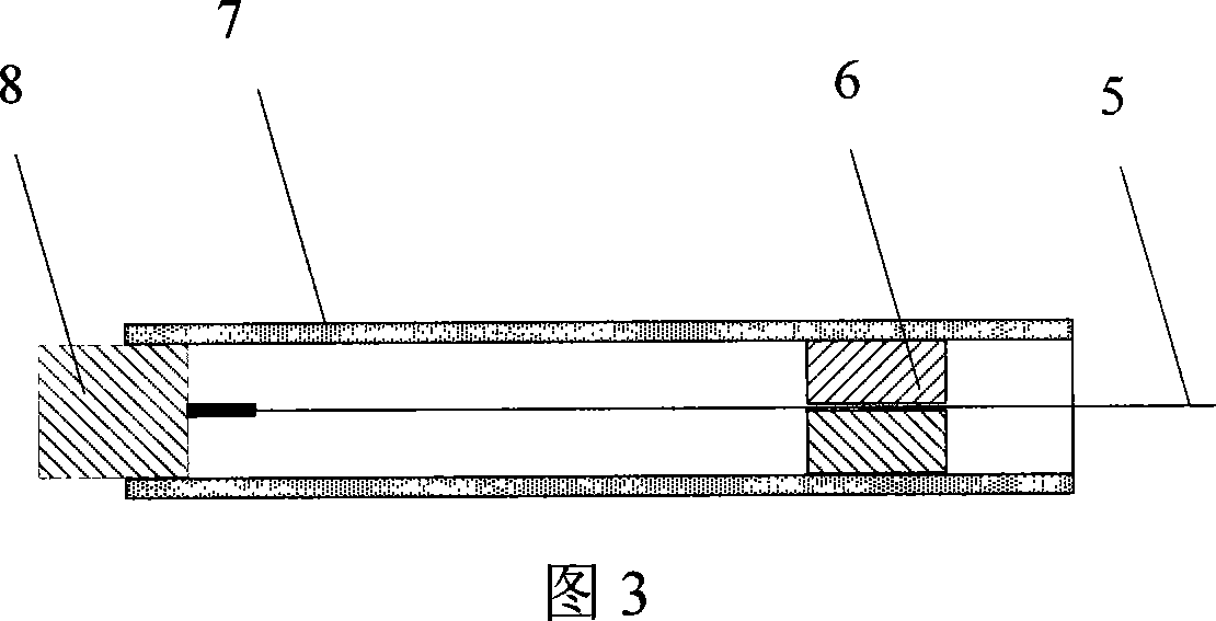
[0018] The structure of the Langmuir probe tip is shown in Figure 3, including: metal tungsten wire 5 (0.175mm in diameter), thin ceramic tube 7 (3mm in diameter), sealing ring 6, tungsten wire connecting contact 8 (metal copper ), where the half of the tungsten wire connecting contact is placed at one end of the thin ceramic tube, the sealing ring is placed at the other end of the thin ceramic tube, and the metal tungsten wire is placed in the center of the thin ceramic tube, in contact with the sealing ring, and connected with the tungsten wire The contact points are connected, and the tungsten wire connection contacts are in contact with the contacts of the Langmuir probe needle body, and the function of the sealing ring is to prevent the contact between the metal tungsten wire and the fine ceramic tube. The Langmuir probe needle body is shown in Figure 4, including: the contact 10 of the Langmuir probe needle body, the compensation electrode 9 (stainless steel drum), the ca...


PUM


Abstract

A low temperature plasma diagnostic equipment relates to plasma diagnostic technology, which aims at the problems that antijamming capability and real-time of the same technology are low. The apparatus comprises langmuir probe, electrical source signal generating circuit, signal collecting circuit and electrical source. The langmuir probe connects to the signal collecting circuit. The signal collecting circuit connects to the electrical source signal generating circuit. The electrical source respectively connects to the electrical source signal generating circuit and signal collecting circuit. The invention has the advantages of low interference to the plasma, low volume, convenient application and real time measure.

Description

technical field [0001] The invention belongs to the technical field of plasma diagnosis, and is particularly used for real-time measurement of relevant parameters of low-temperature plasma, such as electron temperature, electron density, ion density, space potential, suspension potential, Debye length and electron energy distribution. Background technique [0002] There are many methods for plasma diagnosis at present, and the Langmuir probe is one of them with a relatively simple structure. Its characteristic is that it can measure plasma parameters with time and space resolution, and can measure more plasma parameters. The principle of Langmuir probe measuring plasma parameters is that the Langmuir probe (metal electrode with high melting point and large work function) sealed in the vacuum ceramic seal is placed in the plasma generation and reactor (vacuum chamber); the power supply generates a sawtooth wave from positive to negative, which is loaded on the sampling resis...

Claims


Application Information

Patent Timeline
Patent Type & Authority Applications(China)
IPC IPC(8): H05H1/00
Inventor 王庆巴德纯
Owner NORTHEASTERN UNIV
Why Eureka
Try Eureka