Spiral conveyer structure for horizontal centrifugal machine

A technology of screw conveyor and decanter centrifuge, used in centrifuges, centrifuges with rotating drums, etc., can solve the problems of difficult to reach sewage treatment plants, high moisture content of sludge, and slow space reduction.

Inactive Publication Date: 2007-10-24
SHANGHAI CENTRIFUGE INST
View PDF0 Cites 13 Cited by
  • Summary
  • Abstract
  • Description
  • Claims
  • Application Information

AI Technical Summary

Problems solved by technology

[0005] In the design of today's decanter centrifuges, the spiral generally adopts equal pitch, and the equal pitch design technology of the screw conveyor adopted, although the space for the sediment to pass through the spiral drying section becomes smaller, the trend of the space becoming smaller is too slow. A

Method used


Image

  • Spiral conveyer structure for horizontal centrifugal machine
  • Spiral conveyer structure for horizontal centrifugal machine
  • Spiral conveyer structure for horizontal centrifugal machine

Examples


Embodiment Construction

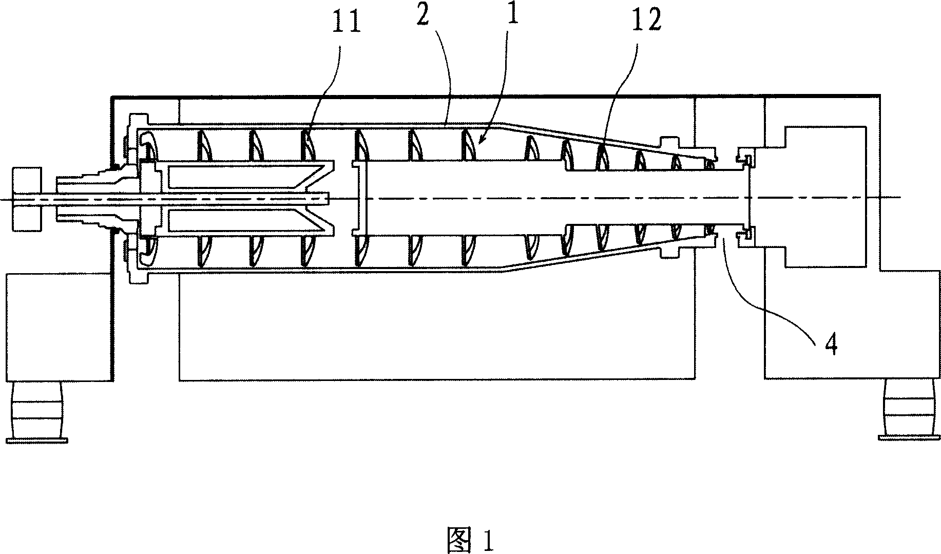
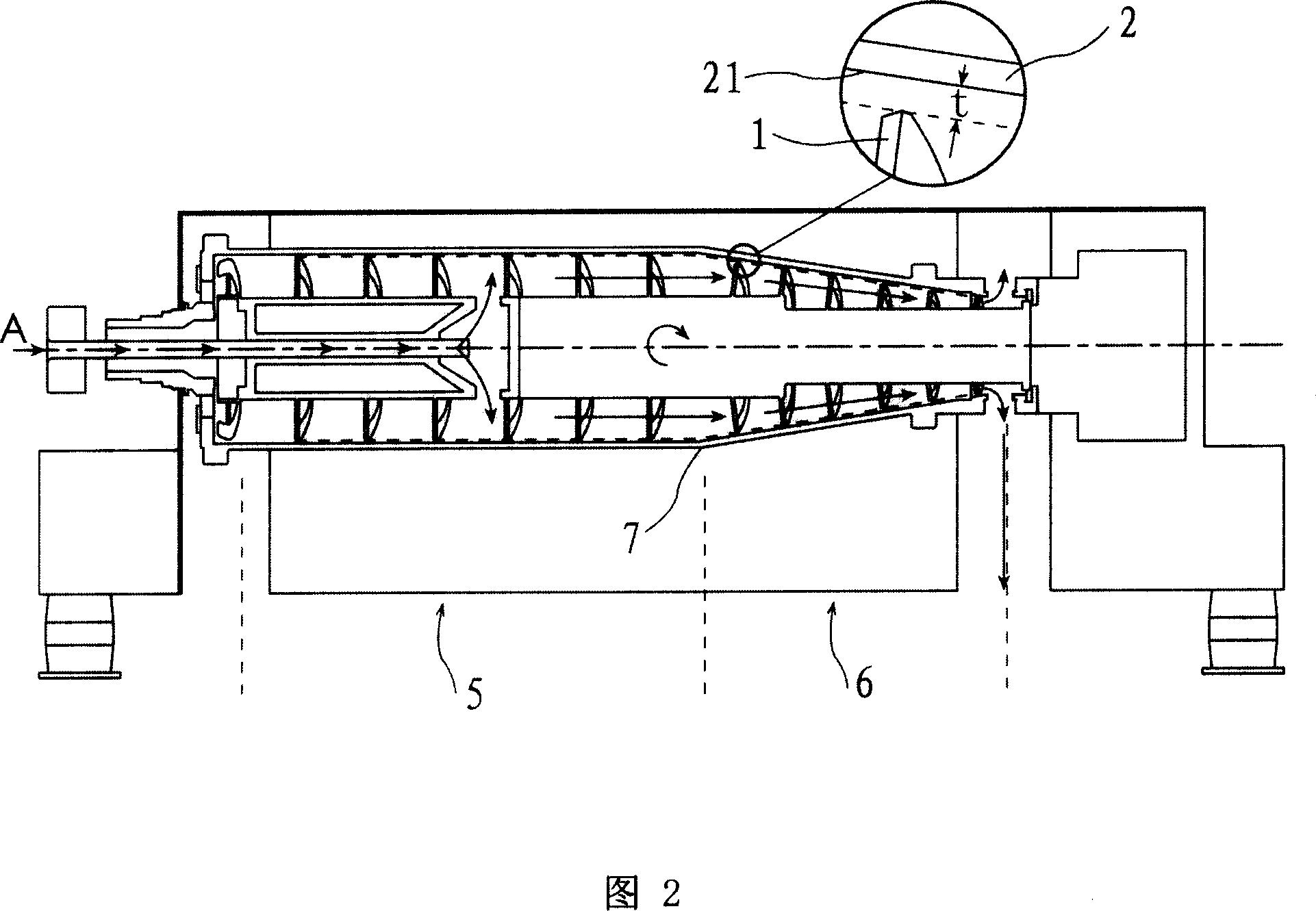
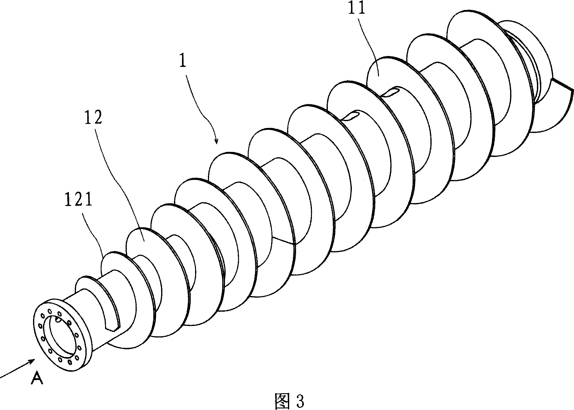
[0017] The screw conveyor structure of a decanter centrifuge according to the present invention mainly involves a screw blade 1 pivotally connected in the supporting drum 2, the screw blade 1 is composed of two naturally connected clarification blades 11 and drying blades 12. Partial composition, as shown in Fig. 1 and Fig. 2 is the decanter centrifuge structure schematic diagram that adopts screw conveyor structure of the present invention;

[0018] The screw conveyor of the decanter centrifuge adopts an equal-pitch design in the straight section (that is, the clarification area 5 of the centrifuge), that is, the pitch of the blade 11 of the clarification section of the screw blade 1 is S=δ (δ is a constant); the cone section of the screw conveyor Part (i.e. centrifuge drying area 6), the pitch is not a fixed value relative to the pitch of the straight section, and the variable pitch design is adopted. The variable pitch design includes two situations: ①, starting from the str...


PUM


Abstract

The invention relates to a horizontal centrifugal spiral transmitter, being a pin pointed spiral vane, which is made of purifying and drying vanes, the form pitch being S=delta(a constant), the latter pitch being S=delta-K (deltais a constant, K is a constant or a constantly adding variable and less than delta). The movement path of the dry vane outer circle on the surface vertical to the projected face of the spiral shaft line can be Archimedian screw. Through pitch changing technique, space for slag going through is greatly reduced than the equal pitch one, with the deposited slag forced outside by the radial centrifugal force, and the squeeze force of the spiral conveyer to both shafts, sludge can be better squeezed and dried, with better separation effect.

Description

technical field [0001] The invention relates to a screw conveyor structure of a decanter centrifuge. Background technique [0002] The decanter centrifuge is a separation machine that relies on the density difference between the solid and liquid phases, and under the action of centrifugal force, accelerates the settling speed of solid phase particles to achieve solid-liquid separation. The decanter centrifuge has the characteristics of continuous operation, large processing capacity, less power consumption per unit output, and strong adaptability; the structure, performance, and parameters of the decanter centrifuge have also changed greatly during decades of development. The quality and production capacity are continuously improved, the application range is wider, and it has a good development prospect. [0003] With the needs of modern environmental protection and the development of three wastes treatment, the requirements for dehydration treatment of industrial wastewate...

Claims


Application Information

Patent Timeline
IPC IPC(8): B04B3/04B04B11/02
Inventor 顾湘徐群
Owner SHANGHAI CENTRIFUGE INST
Why Eureka
Try Eureka