Steel pipe hollow concrete building floor and construction method thereof

A technology of hollow concrete and construction methods, applied in floors, building components, buildings, etc., can solve problems such as easy cracks or cracks, poor anti-consolidation capacity, cumbersome construction process, etc., to overcome cracks or cracks and improve bearing capacity , saving manpower and time

Inactive Publication Date: 2007-10-24
ARCHITECTURAL DESIGN RES INST OF GUANGDONG PROVINCE
View PDF0 Cites 10 Cited by
  • Summary
  • Abstract
  • Description
  • Claims
  • Application Information

AI Technical Summary

Problems solved by technology

[0006] (3). The inner wall of the hollow part of the floor slab has poor pressure resistance and is prone to cracks or cracks
[0007] In addition, during the construction process, formwork is also required: multiple steel pipes are arranged vertically, and the formwork for the floor slab is made on the top of the steel pipes. After the floor slab is poured, the steel pipes used to support the roof are removed. The construction process is cumbersome and expensive. , Long construction period, especially for projects with higher storey height, the cost of supporting the roof is higher

Method used


Image

  • Steel pipe hollow concrete building floor and construction method thereof
  • Steel pipe hollow concrete building floor and construction method thereof
  • Steel pipe hollow concrete building floor and construction method thereof

Examples


Embodiment 1

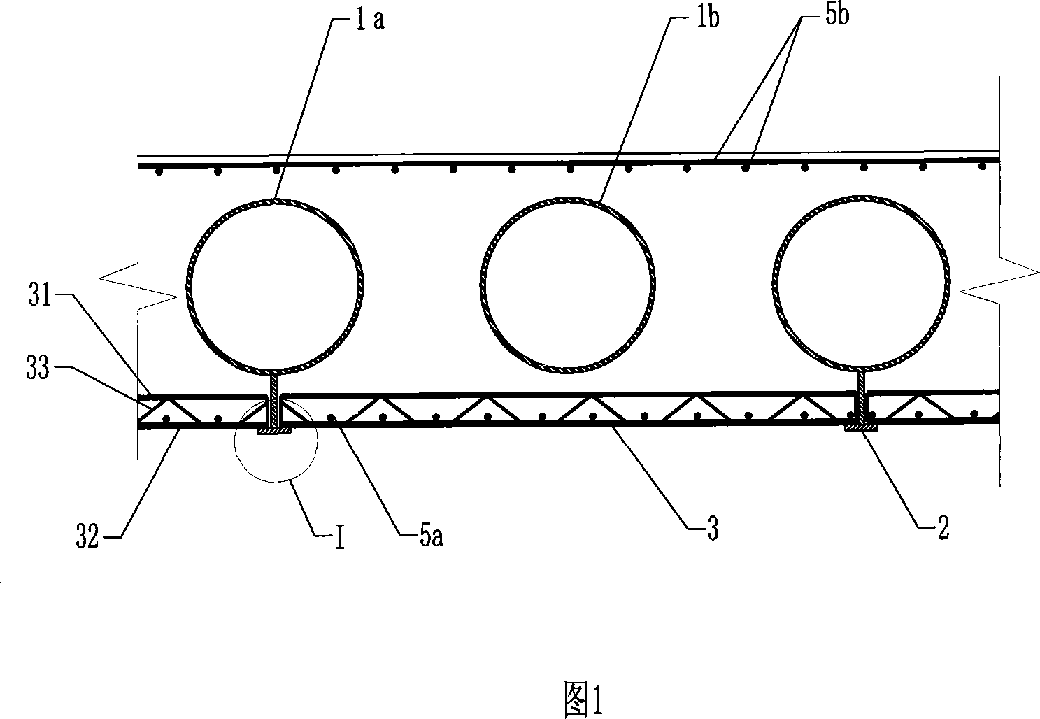
[0134] Embodiment 1 of the present invention, as shown in Figures 1 to 4 and Figures 8 to 13, is a construction method for a steel pipe hollow concrete floor, which specifically includes the following steps:

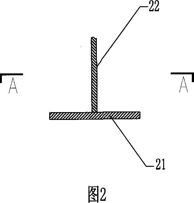
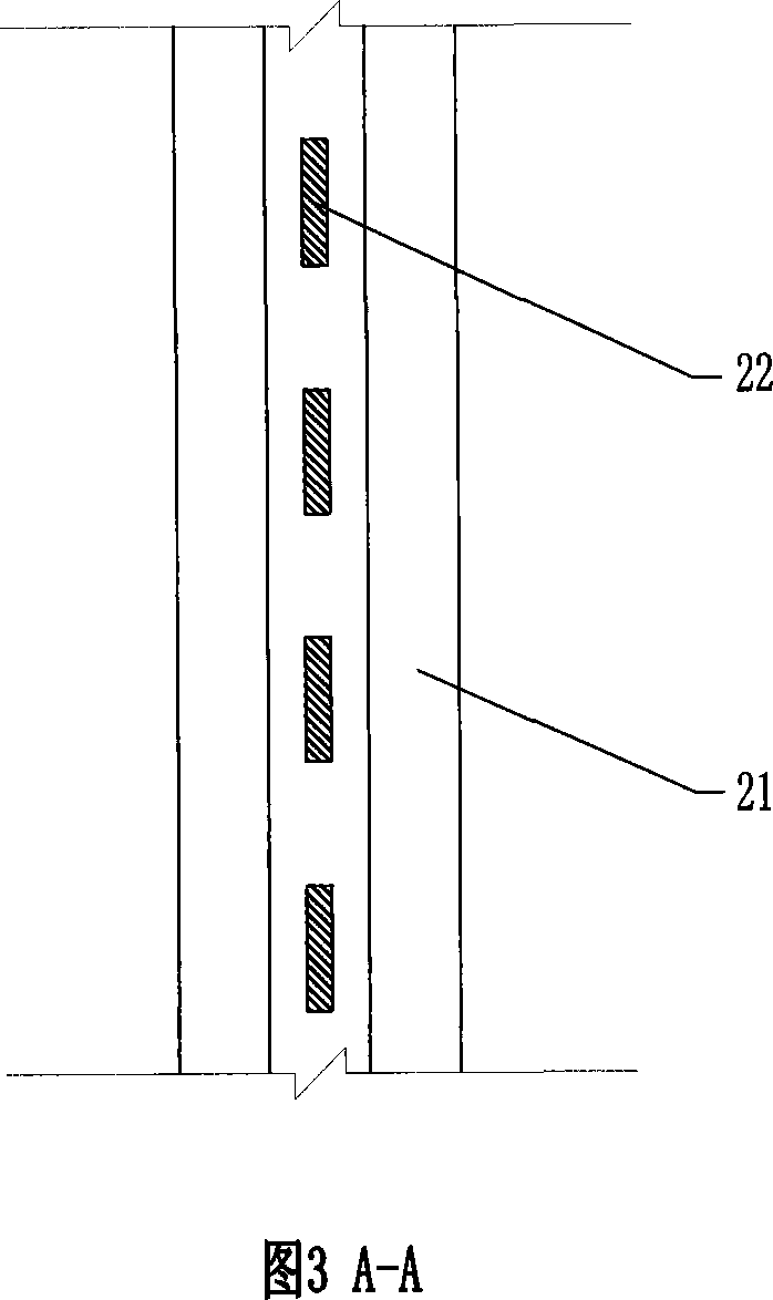
[0135] (1). As shown in Figure 8, two sets of steel pipes 1a and 1b are produced, and one set of steel pipes 1a is fixedly mounted on the bracket 2. The bracket 2 includes a horizontally arranged supporting plate 21 and a vertically arranged hanging plate 22. , the supporting plate 21 is adapted to the length of the steel pipe 1a; the hanging plate 22 is located below the steel pipe 1a, and includes a plurality of vertical plates fixed vertically on the supporting plate 21 and arranged at intervals along the length direction of the supporting plate 21, the vertical plates The upper end of the steel pipe 1a is welded and fixed; first arrange the group of steel pipes 1a in parallel, and let its two ends be welded and fixed to the side wall on the inner side of the square be...

Embodiment 2

[0143] Implementation 2 of the present invention is shown in Figure 5. What is different from the previous embodiment is that in the concrete between the adjacent two steel pipes 1a and 1b, prestressed steel strands 8 are also arranged, and the prestressed steel strands 8 is a concave parabolic shape in the middle, and the two ends of the prestressed steel hinge line 8 pass through the square beam 4, and are fixed on the side wall on the outside of the square beam 4 with bolts 9. In the construction process, in step 4, when installing another group of steel pipes 1b, the prestressed steel strand 8 is pre-embedded and fixed at the same time. Other construction process is identical with embodiment 1.

Embodiment 3

[0145] Embodiment 3 of the present invention is shown in Figure 6. The difference from Embodiment 1 is that a frame beam 10 is also provided in the middle of the floor. The frame beam 10 is perpendicular to the arrangement direction of the steel pipes 1a and 1b. spans the entire width of the slab, but is divided into two zones by a frame beam 10 located in the middle of the slab. In steps 1 and 4 of the construction method, one end of the steel pipe 1a or 1b is respectively fixed on both sides of the frame beam 10 located in the middle, and the other end of the steel pipe 1a or 1b is fixed to the square beams 4 on both sides. Other construction process is identical with embodiment 1.


PUM


Abstract

A steel pipe hollow concrete floor is equipped with a number of steel pipes in itself, the steel pipes are surrounded by concrete structure and forms hollow floor; two ends of the steel pipes are fixed on the frame beam combined with the floor. Said steel pipes not only can be used as the molding template, the poured concrete need not be demounted but as one part of hollow floor. The steel pipe hollow concrete floor in the invention has small floor integral section, light weight and large bearing capacity.

Description

Technical field [0001] The invention relates to a concrete floor slab, in particular to a hollow concrete floor slab suitable for a building with a large load and a large span but limited height. Background technique [0002] Hollow-core slabs made of concrete have long been widely used in houses and bridges. Unfortunately, in the process of making hollow-core slabs, the tubes used for forming never participate in the force of hollow-core slabs. They are only templates for forming hollow-core slabs. That's all. The purpose of making the floor slab hollow is to effectively reduce the weight of the floor slab and save materials. In addition, there are hollow-core slabs designed as seismic structures specifically to reduce seismic forces. [0003] In the prior art, the hollow-core slab can be produced in a factory or on the construction site. When making in the factory, there are usually specially designed molds. After the concrete is initially solidified, the mold is pulled...

Claims


Application Information

Patent Timeline
Patent Type & Authority Applications(China)
IPC IPC(8): E04B5/36
Inventor 陈星罗赤宇向前李欣孙礼军叶浩林扑强王华林欧妍君郭伟杰李娜蒋运林彭思
Owner ARCHITECTURAL DESIGN RES INST OF GUANGDONG PROVINCE
Why Eureka
Try Eureka