A compact multi-frequency antenna

A multi-frequency antenna and frequency band technology, which is applied to antennas, resonant antennas, and devices that enable antennas to work in different bands at the same time, can solve the problem that it is difficult to adapt to the requirements of miniaturization and multi-frequency, and the plane radiation part occupies a large plane area. , volume can not be effectively reduced and other issues

Active Publication Date: 2007-10-24
HTC CORP
View PDF1 Cites 4 Cited by
  • Summary
  • Abstract
  • Description
  • Claims
  • Application Information

AI Technical Summary

Problems solved by technology

However, when this kind of antenna is to be used as a multi-frequency antenna, its planar radiation part needs to occupy a large plane area, and the distance d0 between the radiation plane and the substrate plane (Figure 1) is related to the frequ

Method used


Image

  • A compact multi-frequency antenna
  • A compact multi-frequency antenna
  • A compact multi-frequency antenna

Examples


Embodiment Construction

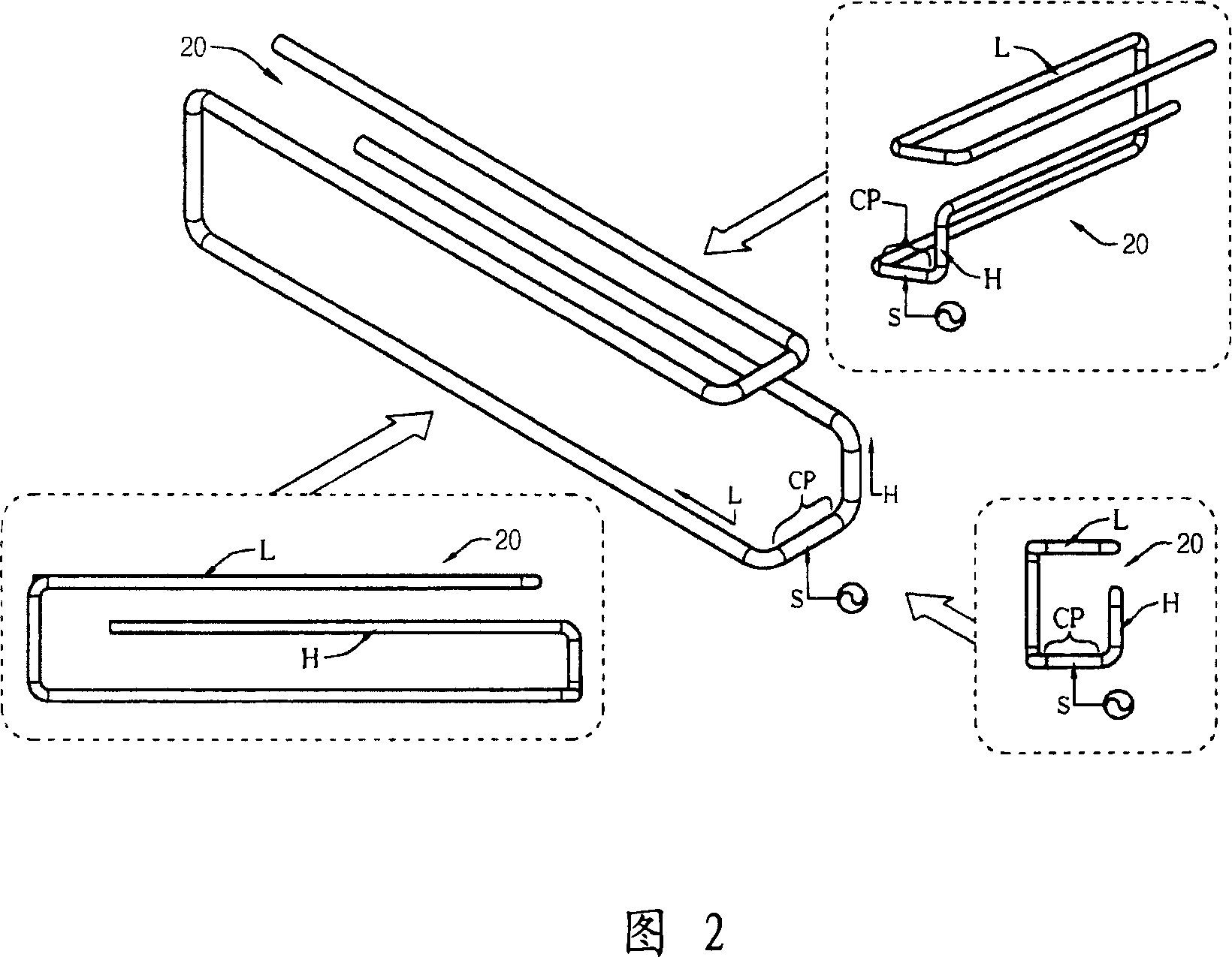
[0031] Please refer to FIG. 2 , which schematically shows an embodiment of an antenna 20 of the present invention in views from different angles. The antenna 20 of the present invention can be a monopole antenna, which is provided with a connection part CP, a low-frequency radiation part L and a high-frequency radiation part H, so that the antenna 20 of the present invention can function as a multi-frequency antenna and support wireless communications in various frequency bands need. As shown in Figure 2, the antenna 20 of the present invention can be formed by twisting a conductor with a uniform cross section (for example, a metal copper wire with a circular cross section), and its low frequency radiation part L and high frequency radiation part H are different from the connecting part CP respectively. The (opposite) two ends start to extend and form a three-dimensional wrapping structure. The connection part CP can accept the feed-in / feed-out of electronic signals through i...


PUM


Abstract

The disclosed miniaturized multi-frequency antenna comprises: a uniform-section conductor connection part for signal I/O, a LF first radiation part on one side of the connection part for forming three main segments along two planes, and a HF second radiation part forming two segments on one plane, wherein the ends of two radiation parts are paralleled for coupling performance. This invention reduces size and improves entire performance.

Description

technical field [0001] The present invention relates to a miniaturized multi-frequency antenna, in particular to a miniaturized multi-frequency monopole (monopole) which has a three-dimensional winding structure and can effectively utilize the mutual coupling characteristics between radiating parts of different frequency bands to improve antenna characteristics antenna. Background technique [0002] In the modern information society, various wireless communication networks have become one of the most important ways for the public to exchange voice or text information, data, materials, and audio-visual files. Access to these wireless communication networks that carry information through wireless electromagnetic waves requires the use of antennas. Therefore, the research and development of antennas has become one of the key points of modern information manufacturers. In order to allow users to integrate and access multiple different wireless communication networks more conven...

Claims


Application Information

Patent Timeline
IPC IPC(8): H01Q5/00H01Q9/30H01Q5/28H01Q5/307
Inventor 陈允达周建邦谢章浩
Owner HTC CORP
Why Eureka
Try Eureka