UPS supply device

A power supply device and storage battery technology, applied in the direction of circuit devices, battery circuit devices, output power conversion devices, etc., can solve problems such as high power loss, increased manufacturing costs, and reduced conversion efficiency of the boost rectifier circuit 120

Inactive Publication Date: 2007-10-24
DELTA ELECTRONICS INC
View PDF0 Cites 8 Cited by
  • Summary
  • Abstract
  • Description
  • Claims
  • Application Information

AI Technical Summary

Problems solved by technology

Since the boost inductors L11 and L22 are magnetic components, a considerable power loss will be caused, thereby reducing the conversion efficiency of the boost rectifier circuit 120.
Furthermore, since a current monitor composed of semiconductor elements needs to be installed on each bus to measure the output current of the bus 10a, 10b respectively, it will cause the problem of increased manufacturing cost.

Method used


Image

  • UPS supply device
  • UPS supply device
  • UPS supply device

Examples


Embodiment Construction

[0042] Preferred embodiments embodying the features and advantages of the present invention will be described in detail in the ensuing description. It should be understood that the present invention is capable of various changes in different forms without departing from the scope of the present invention, and that the description and reference numerals therein are used for illustration in nature and not for limiting the present invention. .

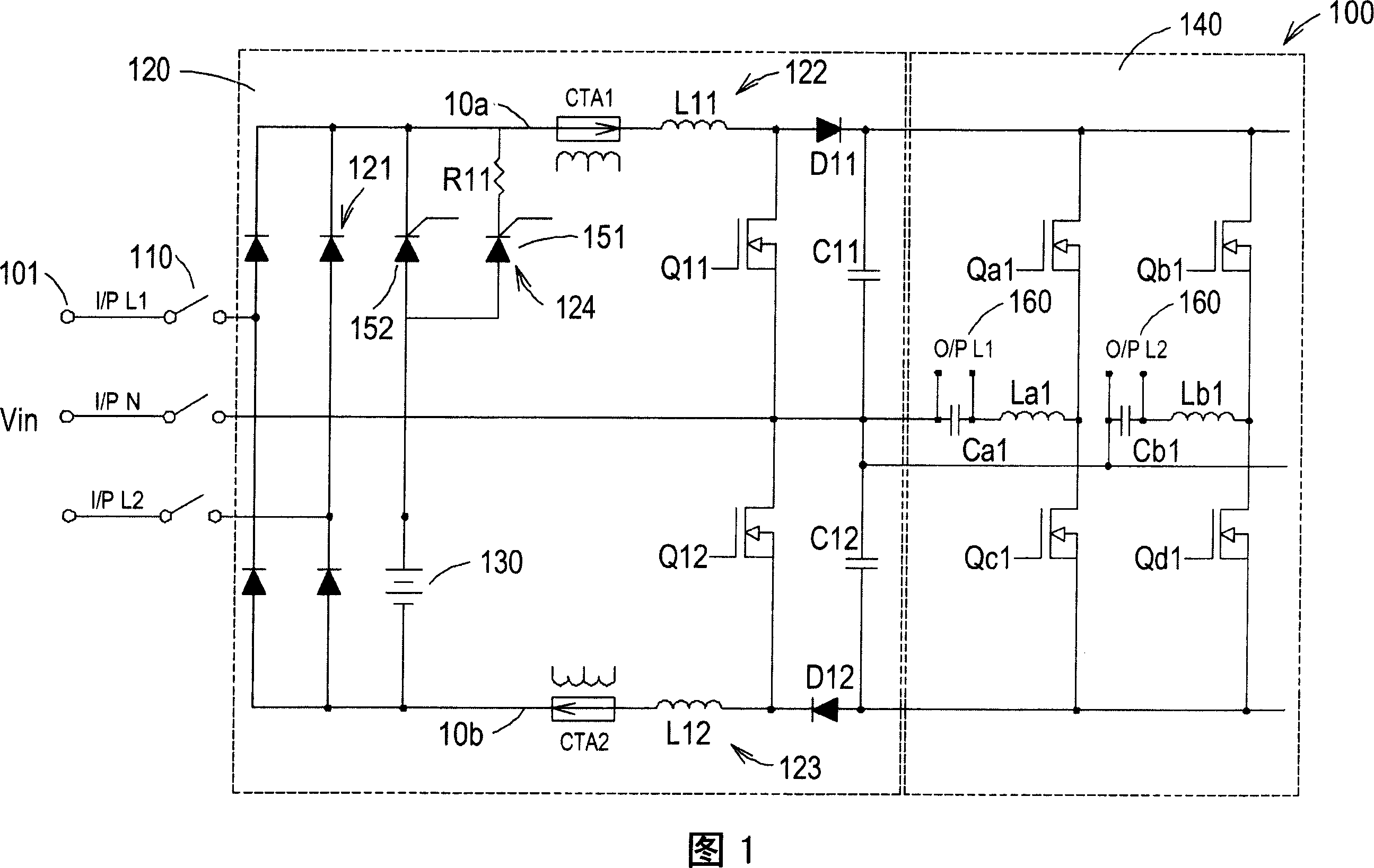
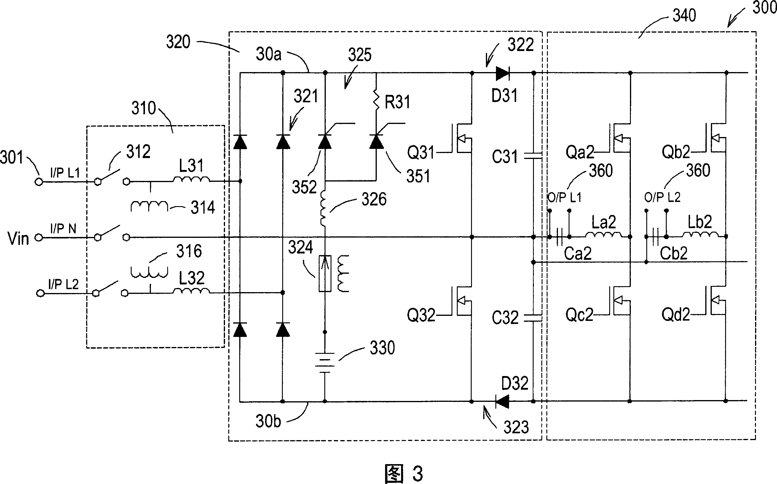
[0043] A first embodiment of the present invention is shown in FIG. 3 . 3 shows an on-line uninterruptible power supply device 300, which includes an input circuit 310, a rectifier circuit 320, a battery 330 and an inverter circuit 340, wherein the rectifier circuit 320, the battery 330 and the inverter circuit 340 are connected via a bus 30a, 30b connection. The input circuit 310 is coupled between the voltage input terminal 301 and the rectifier circuit 320 for receiving the input AC voltage Vin and converting the input AC transformer...


PUM


Abstract

The provided UPS device with low power consumption comprises: an input circuit coupling between the voltage inlet and rectifier circuit, a boost-up inductor at the input circuit being charged by ac current to supply rectifier circuit with the ac voltage, and an inverter conversing the transient dc voltage from the rectifier into multi-phase ac voltage for the load.

Description

technical field [0001] The present invention relates to an uninterruptible power supply (UPS), in particular to an uninterruptible power supply with low cost and low power consumption. Background technique [0002] For various electronic devices, a clean and uninterrupted power supply is the basic condition to maintain their normal operation. In order to avoid the erroneous operation of electronic devices caused by the interruption or abnormality of the AC power supplied by the mains power supply, an uninterruptible power supply (UPS) has been developed to provide a backup when the input AC power of the electronic device cannot supply power normally. Power supply to maintain the operation of electronic devices. [0003] FIG. 1 shows a schematic circuit diagram of a known on-line uninterruptible power supply device, wherein the input AC voltage Vin is provided by a public power supply or a commercial power supply. As shown in Figure 1, a conventional on-line uninterruptible...

Claims


Application Information

Patent Timeline
Patent Type & Authority Applications(China)
IPC IPC(8): H02J7/00H02J7/02H02J7/10H02M7/00
Inventor 赖渊芳张瑛淞
Owner DELTA ELECTRONICS INC
Why Eureka
Try Eureka