Current source inverter with energy clamping circuit and its control method

A technology of current source inverter and clamping circuit, which is applied in the direction of converting AC power input to DC power output, electrical components, output power conversion devices, etc., and can solve problems such as harmonic interference at the mains power supply end and fuse burnout

Inactive Publication Date: 2007-10-24
DELTA ELECTRONICS INC
View PDF0 Cites 13 Cited by
  • Summary
  • Abstract
  • Description
  • Claims
  • Application Information

AI Technical Summary

Problems solved by technology

[0009] For the current source inverter 2 shown in Figure 3(a), when the DC input power supply V_in has not been established, if it is plugged into the mains power supply, a large inrush current (inrush current) will be generated through D_A and D_D or D_B and D_C flows to the input capacitor C_in, this impact current will not only burn the fuse at the mains power supply end, but also easily cause harmonic interference to the mains power supply end

Method used


Image

  • Current source inverter with energy clamping circuit and its control method
  • Current source inverter with energy clamping circuit and its control method
  • Current source inverter with energy clamping circuit and its control method

Examples


Embodiment Construction

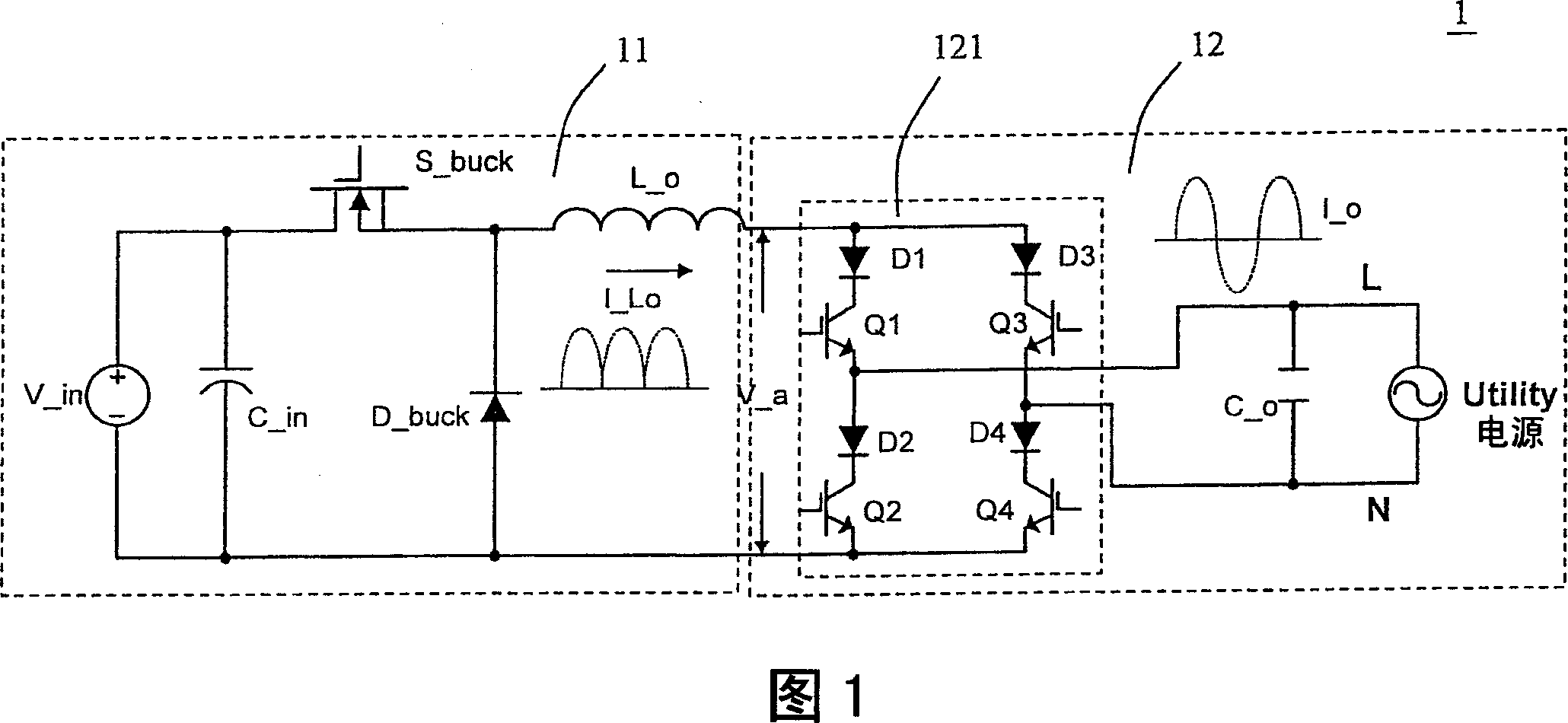
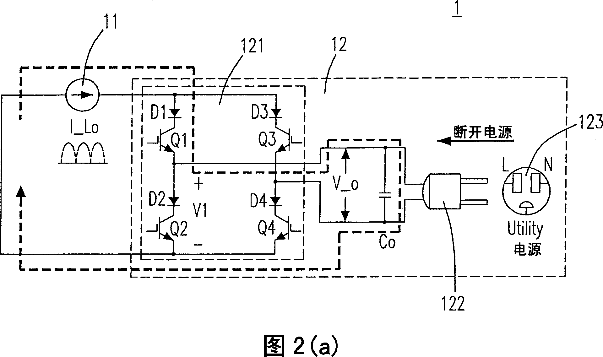
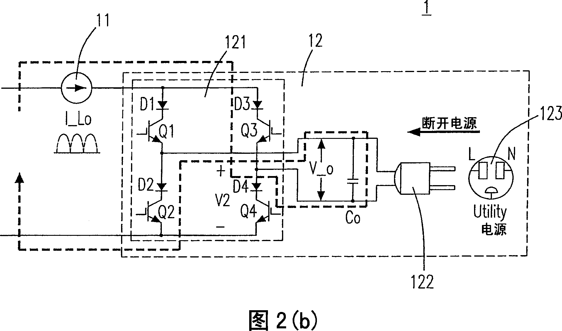
[0070] Please refer to Fig. 5 (a), which shows the circuit of the first preferred embodiment of the current source inverter comprising the energy clamping circuit and the positive half cycle path of the impact current according to the present invention with relatively better effect A schematic diagram of the current flow. Wherein, the current source inverter 3 comprising the energy clamping circuit with better effect includes: step-down converter 11 and DC / AC converter 12 with switching bridge circuit 121, plug 122 and socket 123 (for providing The mains power supply) is the same as that described in the foregoing Fig. 3(a) to Fig. 3(c), and also includes an energy clamping circuit 31, and the energy clamping circuit 31 includes: a plurality of diodes 311 (by the first Diodes one to four: composed of D_A, D_B, D_C and D_D, which are the same as 21 in FIG. 3( a )) and a switch 312 . The positive half-cycle discharge path of the surge current is the same as that shown in FIG. 4...


PUM


Abstract

The disclosed current source inverter with energy clamp circuit comprises: a voltage-reduced translator with input capacitor and output inductor to receive the dc input voltage and output induction current, a dc / ac converter with output capacitor to receive the last current and generate ac current, a load coupling with the dc / ac converter to provide discharge path and avoid impulse current, and an energy clamp circuit including two diodes. This invention reduces the voltage stress on transistors greatly, and avoids the generation of impulse current.

Description

technical field [0001] The invention relates to a current source inverter with an energy clamping circuit and a control method thereof, in particular to a current source inverter with a better energy clamping circuit and a control method thereof. Background technique [0002] A known current source inverter (current source inverter) 1 (as shown in FIG. 1 ) is a current source output and can be directly connected in parallel with a commercial power supply. The current source inverter 1 includes a step-down converter 11 and a DC / AC converter 12 . The step-down converter 11 further includes: an input capacitor C_in, a step-down converter switch S_buck, a slow diode D_buck, and an output inductor L-o for receiving the DC input voltage V_in and generating the output inductor current I_Lo. The DC / AC converter 12 also includes: a switching bridge circuit 121, including four unidirectional switches and an output capacitor C_o, and the four unidirectional switches are: D1+Q1, D2+Q2,...

Claims


Application Information

Patent Timeline
Patent Type & Authority Applications(China)
IPC IPC(8): H02M7/515
Inventor 詹智强张育铭
Owner DELTA ELECTRONICS INC
Why Eureka
Try Eureka