A static discharge protective circuit with the feedback technology

An electrostatic discharge protection and circuit technology, applied in the direction of static electricity, electrical components, etc., can solve problems such as circuit error triggering

Inactive Publication Date: 2007-10-24
SILICON INTEGRATED SYSTEMS
View PDF0 Cites 16 Cited by
  • Summary
  • Abstract
  • Description
  • Claims
  • Application Information

AI Technical Summary

Problems solved by technology

However, such circuits still have some problems
Such a circuit may still be falsely triggered for fast charging, for example

Method used


Image

  • A static discharge protective circuit with the feedback technology
  • A static discharge protective circuit with the feedback technology
  • A static discharge protective circuit with the feedback technology

Examples


Embodiment Construction

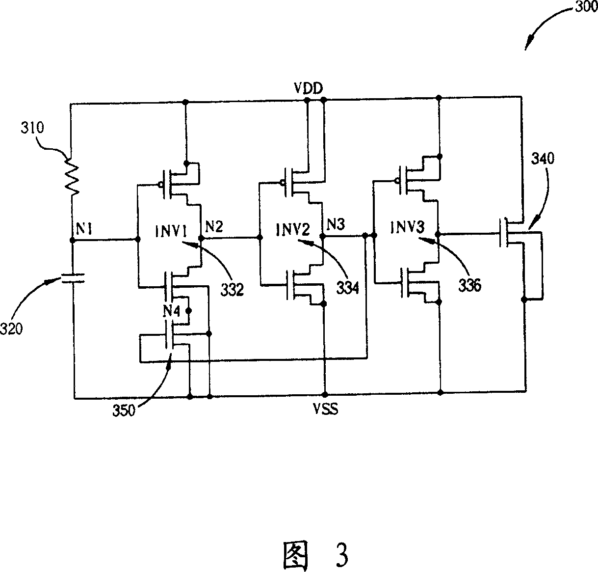
[0015] Please refer to FIG. 3 , which is a schematic diagram of an ESD protection circuit 300 according to a first embodiment of the present invention. As shown in Figure 3, the electrostatic discharge protection circuit 300 includes a resistance component 310, a capacitor component 320, an inverter group, a metal oxide semiconductor field effect transistor (MOSFET) 340, and an N-type metal oxide semiconductor field An effective transistor 350, wherein the inverter group includes inverters 332, 334 and 336. The resistor element 310 is coupled between the voltage level VDD and the node N1. The capacitor element 320 is coupled between the node N1 and the voltage level VSS. The MOSFET 340 has a first terminal, a second terminal and a third terminal, wherein the first terminal is coupled to the voltage level VDD, and the second terminal is coupled to the voltage level Level VSS. The inverter group composed of inverters 332, 334 and 336 has an input terminal and an output termin...


PUM


Abstract

The static-electricity discharge protective circuit comprises: a resistor coupling between a first voltage and node N1, a capacitor coupling between a second voltage and node N1, a first transistor with first / second / third end coupling with first / second-voltage / node N2, a phase inverter group with inlet coupling N1 and outlet coupling N2, and a second transistor with first end coupling with the first phase inverter, a second end coupling with second voltage, and a third end coupling with the second inverter. The outlets of two inverters relate to different logic levels.

Description

technical field [0001] The invention relates to an electrostatic discharge protection circuit, in particular to an electrostatic discharge protection circuit with feedback technology. Background technique [0002] The electrostatic discharge protection circuit (ESD circuit) is used to provide a low-impedance current path to lead out the electrostatic current. FIG. 1 shows an RC trigger ESD protection circuit based on a metal oxide semiconductor field effect transistor (MOSFET). Due to the good performance of this circuit structure, it has been widely used in many applications. Generally speaking, the main design considerations of existing ESD protection circuits include layout area, start-up current, leakage current from VDD to VSS, and an avoidance mechanism for false triggering in operation. In addition, the trigger time of the protection circuit is a critical design parameter. As shown in FIG. 1 , the ESD protection circuit 100 includes a resistor 110 , a capacitor 120...

Claims


Application Information

Patent Timeline
IPC IPC(8): H05F3/04
Inventor 李健铭柯明道
Owner SILICON INTEGRATED SYSTEMS
Why Eureka
Try Eureka