Three-dimensional measuring machine for the shoe mould

A technology of three-dimensional measurement and shoe molding, which is applied to the measurement devices of feet or shoe lasts, footwear, and other applications. It can solve the problems of high trial processing costs, high physical energy consumption, and low efficiency, and achieve simple and convenient use of the machine. Installation Ease of use, lower entry level effect

Inactive Publication Date: 2007-10-31
翁清铿
View PDF2 Cites 39 Cited by
  • Summary
  • Abstract
  • Description
  • Claims
  • Application Information

AI Technical Summary

Problems solved by technology

[0006] Production practice has proved that this production method is suitable for some daily necessities\mechanical products with relatively simple appearance and structure, but it is used to deal with round and extremely irregular sole samples. The disadvantages are obvious: 1) Low efficiency, It takes two experienced hands more than two days to sort out a medium-difficulty 2D map, and it takes about seven days to construct a 3D model
The delivery cycle of a mold is only more than 20 days, including the time of mold trial and mold modification, because most of the cutting processes cannot greatly shorten the processing time under the current machine tool technology conditions, so under the same process, it can be Greatly improving the efficiency of three-dimensional input is equivalent to shortening the molding cycle of the mold; 2) almost all the sample soles are soft materials, and the shape changes continuously during the scanning measurement, so it is impossible to determine a suitable measurement state; When the bottom and surrounding areas are scanned separately, five groups of highly random placements cannot provide accurate correction benchmarks for the subsequent 2D image file arrangement; 3) Low modeling accuracy: 2D image arrangement is mainly based on photos and card boards Scanning is the main method, and there are many discrepancies with the sample to be

Method used


Image

  • Three-dimensional measuring machine for the shoe mould
  • Three-dimensional measuring machine for the shoe mould
  • Three-dimensional measuring machine for the shoe mould

Examples


Embodiment Construction

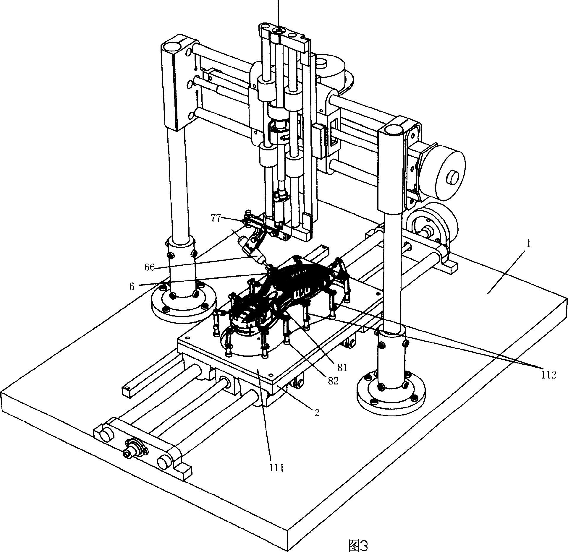
[0056] As shown in Fig. 3, the working principle of the present invention is: fix the sample shoe 81 on the surveying tool 82 according to the appropriate position, and then fix the surveying tool on the workbench 2 of the measuring machine through the part screw hole 80. When the control handle is manipulated, the three axes of the measuring machine can move accordingly. At this time, the position detection element parallel to the three axes of the machine—the grating can continuously send the position pulse signals of each axis to the digital display meter. The digital display meter has a built-in single-chip control circuit, which can convert these signals into digital coordinates and display them on the panel. In addition, the digital display meter can complete functions such as coordinate clearing and number setting, which are used to complete benchmark calibration before surveying and mapping and change the probe post-baseline calibration. During the surveying and mappin...


PUM


Abstract

The invention discloses a three-dimensional measuring machine of shoe die, which is characterized by the following: comprising surveying work assembling system, feeding control system, mechanical motor system and controlling PC machine; arranging the surveying work assembling system on the work bench of the mechanical motor system to fix the sample shoe; controlling the feeding direction of three axis movement and speed with the feeding control system; adjusting the measuring time-effect and accuracy; touching the sample shoe with the metering needle of needle measuring head on the mechanical control system; collecting coordinate on the surface of the sample shoe; sending a impulse signal to digital display meter at the time of touching the sample; receiving the impulse signal with digital display meter; recording; sending to the controlling PC machine; deacidizing a same three-dimensional die of the sample shoe with the inverting software on the controlling PC machine.

Description

Technical field: [0001] The invention relates to a three-dimensional measuring machine, in particular to a three-dimensional measuring machine for shoe molds and a measuring method. Background technique: [0002] We know that sports shoes are one of the essential daily necessities in every country, and it is also a pillar industry in the economically developed southeast coastal areas of our country, which can earn hundreds of millions of foreign exchange for our country every year. Shoe molds are an important piece of equipment in the shoe industry. The mold quality, production cycle, and cost are directly related to the production efficiency of sports shoes, the speed of new product sample opening, and the market competitiveness of product price performance. Our country is already a big country of shoe industry production now, but not a big country of technology. The production technology and process of shoe molds need to be improved urgently, especially in the past ten ye...

Claims


Application Information

Patent Timeline
IPC IPC(8): A43D1/08G05B17/00
Inventor 翁清铿
Owner 翁清铿
Why Eureka
Try Eureka