
Electric-controlled head

A pan-tilt, electronic control technology, applied in the machine/stand, control using feedback, supporting the machine, etc., can solve the problems of stability and complicated and inaccurate operation, inaccurate rotation position, motor jitter, etc., to meet the High-precision display and controllable, low-cost effects

Inactive Publication Date: 2007-10-31
UNIV OF SCI & TECH BEIJING
View PDF0 Cites 30 Cited by
  • Summary
  • Abstract
  • Description
  • Claims
  • Application Information

AI Technical Summary

Problems solved by technology

Since the step angle of the stepping motor is generally relatively large, although intermittent pauses, frequent changes of forward rotation, reverse rotation, and positioning can be realized, the measurement and control accuracy is not high
Due to the use of pulse current drive, special circuits and single-chip microcomputer programming control are required. When the speed is low, it is easy to cause the vibration of the motor. When driving a large load, it is easy to lose steps, resulting in inaccurate rotation positions. Long-term use leads to errors. In order to eliminate the error, the initial position and accuracy can only be restored by power-off and restarting. The stability and operation of long-term work are both cumbersome and inaccurate

Method used


Image

  • Electric-controlled head
  • Electric-controlled head
  • Electric-controlled head

Examples


Embodiment 1

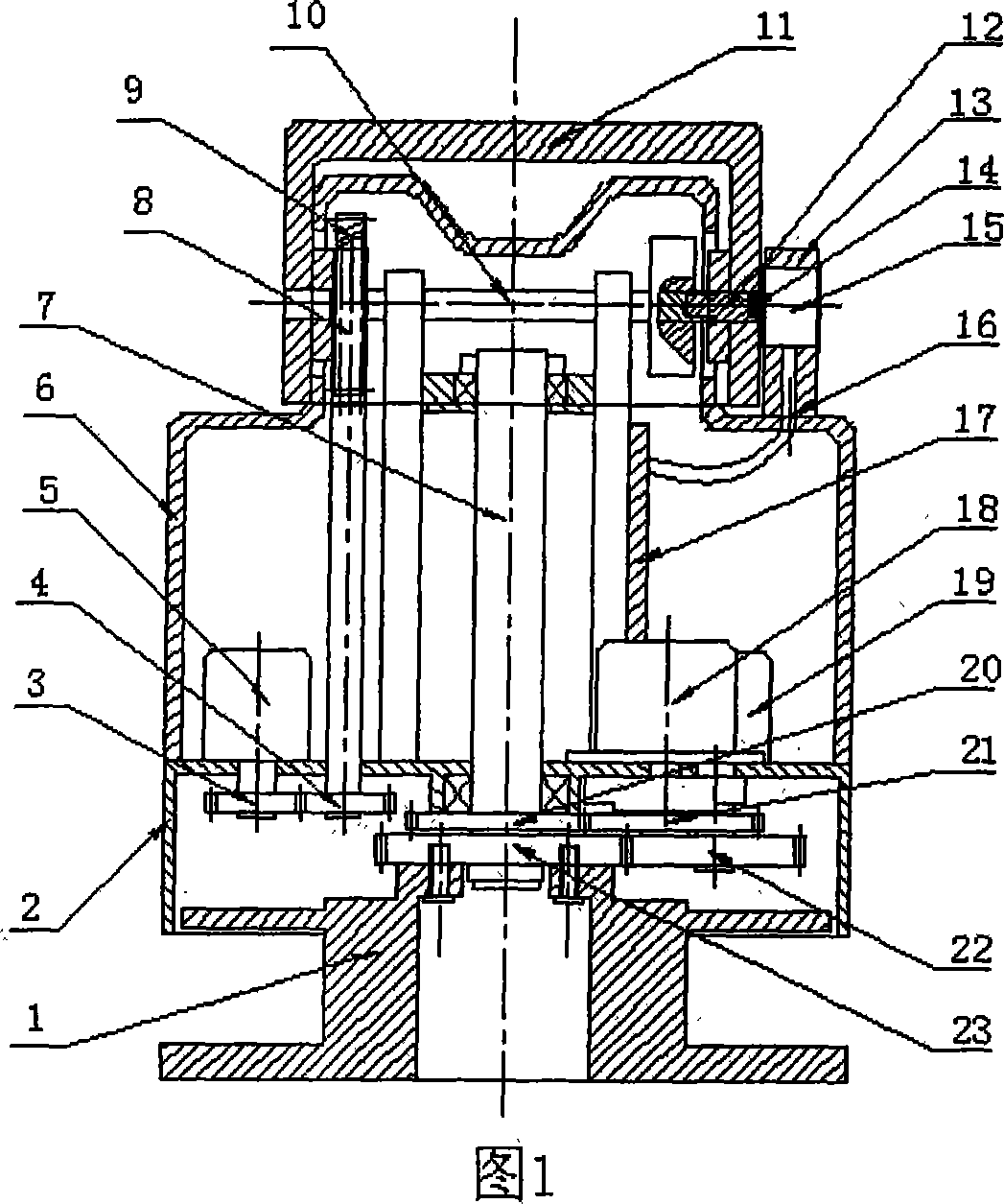
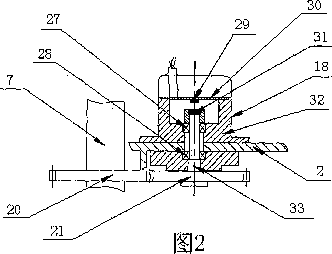
[0029] As shown in Figure 1, the structure of the integrated magnetic-sensitive angle sensor 18 used for plane rotation angle detection in the present invention is shown in Figure 2, and the sensor rotating shaft 33 is fixed on the outer end cover 32 by two rotating bearings 27,28, and the outer diameter is Φ34mm. One end of the rotating shaft 33 is fixed with a special magnetic field 31, and the programmable magneto-sensitive integrated chip 29 is installed on a position corresponding to the signal processing circuit board 30 of the programmable magneto-sensitive integrated chip with a diameter of Φ22 mm. It is concentrically mounted on the end cap 32 of the sensor 18 at a selected value interval of 0.1-20 mm. 18 shaft ends of the plane rotation angle sensor and the 7 shaft ends of the non-rotating central shaft of the cloud platform are additionally installed with a gear ratio 1: 1, and a synchronous gear 20,21 whose modulus is 1. When the driving motor makes the pan-tilt r...

Embodiment 2

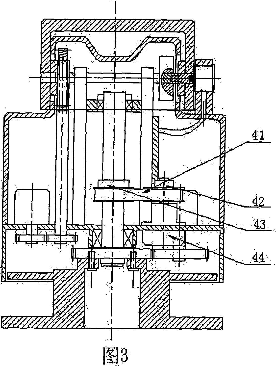
[0033] Use the method of synchronous pulley to measure the plane rotation angle of the pan-tilt, as shown in Figure 3. The synchronous pulley type plane rotation angle sensor 44 is shown in FIG. 4 . A pair of synchronous belt pulleys 42,43 with convex and concave teeth having the same outer diameter are respectively fixed on one end of the plane rotation angle sensor 44 rotating shaft 34 on the rotating lower end cover 2 of the cloud platform, corresponding to the position of the same height as the stationary rotating shaft 7 of the platform. The synchronous wheels 42 and 43 are tightened by the synchronous belt 41 to transmit the pan-tilt plane rotation. The rotating shaft 34 is fixed on the end cover 38 in the plane angle sensor 44 by two bearings 35 and 36 . The other end of the rotating shaft 34 is equipped with a special magnetic field 37, and the magnetic encoder type magnetic sensitive integrated chip 39 is installed on the position corresponding to the signal processi...


PUM


Abstract

A electrically control cloud platform for bearing the detecting or displaying apparatus, belong to the sensor field, which is characterized in that it is based on the common cloud platform and provided with a specific signal trigger magnetic field and high-precision magnetosensitive contactless angle sensor in the mechanic structure of plane-rotation and pitching angle rotation of the common cloud platform, to receive the output of electrical signal corresponding to the rotating angle during the rotating in the horizontal direction and pitching direction and realize the detecting and control of rotating area, rotating velocity and precise positioning by the process of microcontroller and control circuit, to satisfy the market demand for the use of a plurality of cloud platforms of high-precision displaying and controlling with low cost.

Description

Technical field: [0001] The invention belongs to the field of sensors and instruments, in particular to an electronically controlled pan-tilt for carrying monitoring or displaying instruments. Background technique: [0002] The pan / tilt is a common component that carries monitoring or display instruments and drives them to rotate. It can often be equipped with various displays, cameras, video cameras, monitoring instruments, aiming and positioning instruments, launching devices, laser light sources, etc., and drives them to generate The plane and tilt rotation can enable the observer to obtain dynamic observation images. [0003] Conventional gimbals currently on the market can only provide a pre-designed single speed plane rotation and pitch rotation. Its rotation angle area only relies on the reversing mechanical collision switch or the proximity switch to generate the reversing control signal, so that the control motor in the pan / tilt can change the rotation direction an...

Claims


Application Information

Patent Timeline
IPC IPC(8): F16M11/00G05D3/20
Inventor 田跃李杰郭志文魏少峰焦旭邱宏潘礼庆
Owner UNIV OF SCI & TECH BEIJING
Learn More