Photographic camera focusing device for mobile phones

A technology for cameras and mobile phones, which is applied in the field of camera focusing devices for mobile phones. It can solve the problems of increasing motor friction resistance, reducing transmission efficiency, large optical axis direction and radial size, etc., and achieves reduction in radial size, size reduction, The effect of simple structure

Inactive Publication Date: 2007-10-31
天津好福来科技发展有限公司
View PDF1 Cites 11 Cited by
  • Summary
  • Abstract
  • Description
  • Claims
  • Application Information

AI Technical Summary

Problems solved by technology

But, there is following problem in this focusing device of prior art: As mentioned above, because the transmission between the motor on this focusing device and the lens barrel 71 is through the pin groove on the pin 80 on the rotor and the lens barrel 71 In this way, transmission clearance will inevitably be generated, thereby reducing the transmission accuracy, and the pin 80 and the pin groove will also generate friction due to relative movement, thereby reducing the transmission efficiency
In addition, the optical axis and radial constraints of the rotor on the motor, that is, the magnet, are realized by a confinement ring that surrounds the outer peripheral surface of the magnet. It will increase the frictional resistance of the motor, thereby reducing the transmission efficiency
In addition, the motor in this focusing device is a stepping motor, and its step distance determines the distance that the lens barrel 71 moves along the optical axis direction, so it is impossible to perform small adjustments smaller than the step distance.
In particular, the feed mechanism in this focusing device is arranged at one end of the motor along the optical axis, and the lens barrel needs to protrude out of the main body when focusing, and a support body for setting the motor is required, so the whole device The optical axis direction and radial dimension are too large, so it is not suitable for application on mobile phones

Method used


Image

  • Photographic camera focusing device for mobile phones
  • Photographic camera focusing device for mobile phones
  • Photographic camera focusing device for mobile phones

Examples


Embodiment Construction

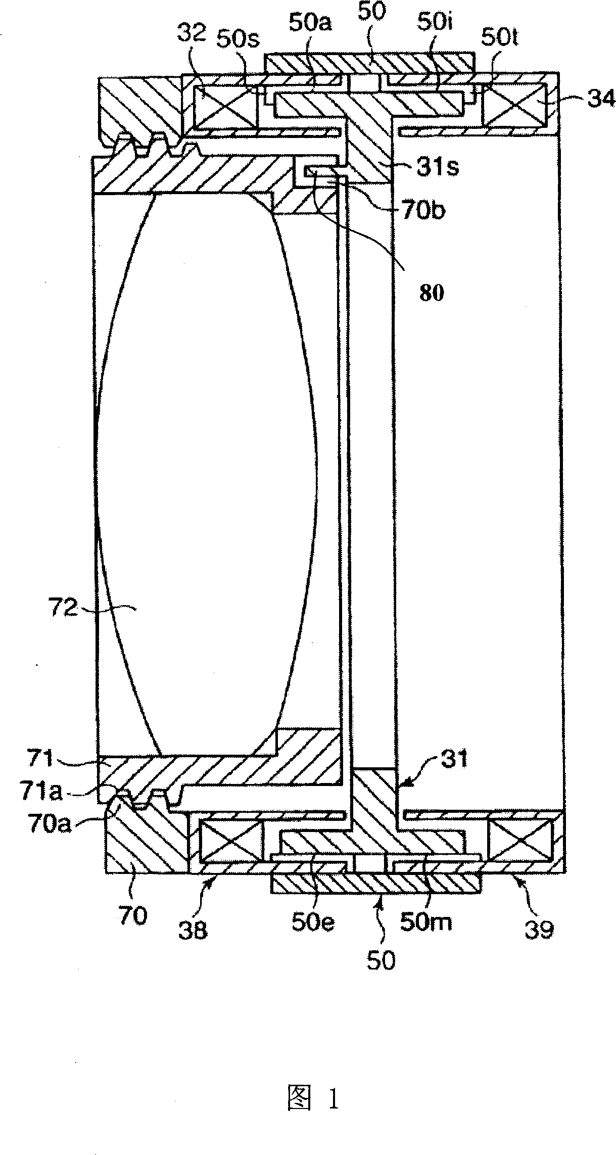
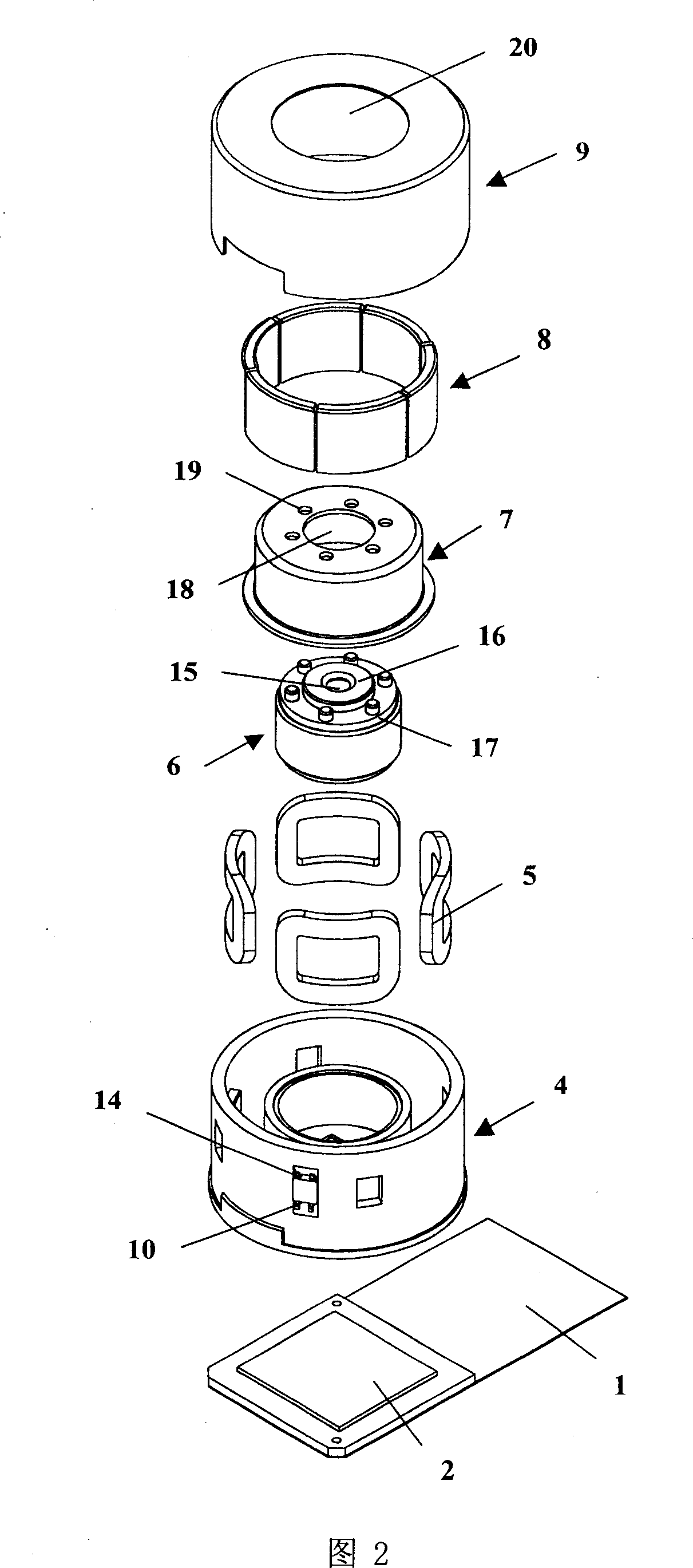
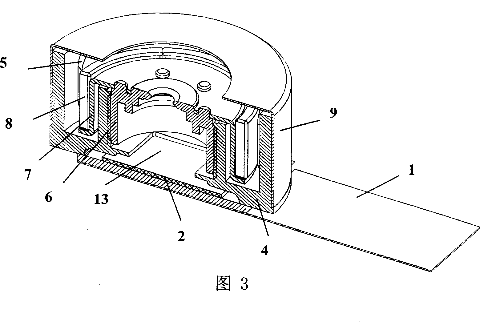
[0025]The mobile phone camera focusing device provided by the present invention will be described in detail below in conjunction with the accompanying drawings and embodiments. As shown in Figures 1 to 7, the mobile phone camera focusing device provided by the present invention includes a flexible circuit board 1, a sensor 2, an infrared filter 3, a base 4, 4 coils 5, a lens barrel 6, and a magnet holder 7 , 6 pieces of magnets 8, upper cover 9 and 2 Hall elements 10; wherein the flexible circuit board 1 is installed on the main circuit board located inside the mobile phone; the sensor 2 is arranged on the surface side of the flexible circuit board 1; The base 4 on the upper part of the plate 1 is in the shape of a double-layer cylinder connected by the bottom surface, wherein the height of the outer cylinder 11 is greater than that of the inner cylinder 12, and the inner peripheral surface of the inner cylinder 12 is formed with internal threads, and the central part of the bo...


PUM


Abstract

This invention relates to cell phone cameral focus adjusting device, which comprises flexible circuit board, sensor, infrared filter slice, bottom socket, four coils, lens cylinder, magnetic sustain rack, six slices of magnetic iron, upper cover and two hall element, wherein this invention provides cell phone cameral focus adjusting device forms feed part composed of magnetic iron, coil and Hall element on outer cylinder to form driver part; the bottom socket inner cylinder screw seam lens, magnetic iron sustain rack and magnetic iron forms feed part; by use of Hall element outputs level connection coil current to generate magnetic force between coil and magnetic iron to keep adjusting operation for move along light axis.

Description

technical field [0001] The invention relates to a focusing device, in particular to a camera focusing device for a mobile phone which can move a lens barrel along the optical axis direction to complete an automatic focusing action. Background technique [0002] At present, with the continuous development of mobile phone design technology and the increasing requirements of users for the diversification of mobile phone functions and the trend of miniaturization, having a camera function has become one of the basic functions of mobile phones. Focusing device with high transmission efficiency, low energy consumption, fine adjustment and small optical axis direction and radial size. The focusing device usually consists of a stepping motor and a feeding mechanism. Japanese Unexamined Patent Publication No. 2002-51524 discloses a focusing device. Fig. 1 is a partial structural sectional view of such a focusing device in the prior art. As shown in Fig. 1, the hollow stepping moto...

Claims


Application Information

Patent Timeline
Patent Type & Authority Applications(China)
IPC IPC(8): G02B7/04H02K37/00G03B13/36
Inventor 严国华
Owner 天津好福来科技发展有限公司
Why Eureka
Try Eureka