MPU FPGA verification device supporting stochastic instruction testing

A microprocessor and verification device technology, applied in the field of microprocessor design verification, can solve problems such as not providing support, and achieve the effect of fast test speed

Active Publication Date: 2007-10-31
LOONGSON TECH CORP
View PDF0 Cites 21 Cited by
  • Summary
  • Abstract
  • Description
  • Claims
  • Application Information

AI Technical Summary

Problems solved by technology

However, such a detection mechanism does no

Method used


Image

  • MPU FPGA verification device supporting stochastic instruction testing
  • MPU FPGA verification device supporting stochastic instruction testing
  • MPU FPGA verification device supporting stochastic instruction testing

Examples


Embodiment Construction

[0032] Below in conjunction with accompanying drawing and specific embodiment the present invention is described in further detail:

[0033] In this embodiment, taking the design verification of the Loongson-2 microprocessor as the verification object, the microprocessor FPGA verification device supporting random instruction testing of the present invention is described in detail. According to the detailed description of this embodiment, those skilled in the art are capable of manufacturing a device for performing design verification on different microprocessors.

[0034] The production of the microprocessor FPGA verification device is divided into two main stages, the first is the production of the system main board, and then the logic design of the main control circuit on the main board.

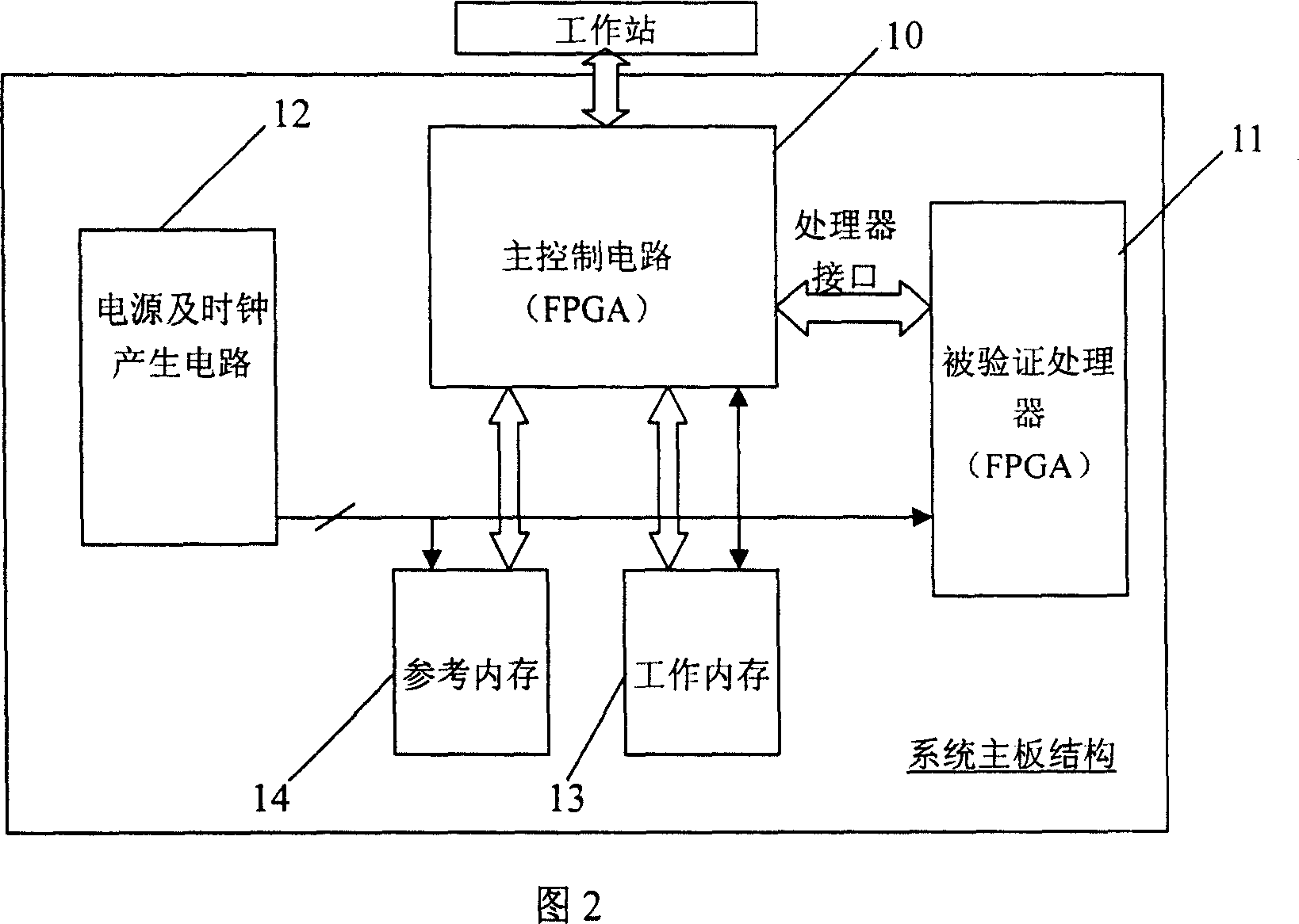
[0035] Production of the system board:

[0036] The structure of the system board is shown in Figure 2. The mainboard can ensure the hardware environment for the correct operation of the...


PUM


Abstract

This invention discloses one artificial valuation FPGA physical prototype validation device through micro processor design, wherein the device comprises the following parts: one main control circuit with one processor interface for connection with validation micro processor; one power and clock generation circuit connected with micro process to be tested; one work memory and one reference memory connected to main control circuit through main control circuit memory interface, wherein the main control circuit has one communication interface with one outer work station.

Description

technical field [0001] The invention relates to microprocessor design verification, in particular to an FPGA (Field Programmable Gates Array, FPGA for short) physical prototype verification device in the simulation verification of general microprocessor design. Background technique [0002] At present, in the functional verification of general-purpose microprocessor design, dynamic simulation is still the dominant verification method. Dynamic simulation verification mainly includes software HDL (Hardware Description Language, HDL for short) simulation and hardware FPGA physical prototype simulation. The advantages of using software HDL simulation method: first, the flexibility of using software simulation is high, and simulation verification can be carried out at various levels of design module level, microarchitecture level and system level; second, the use of software simulation The method can provide a very good debugging environment. Usually, a graphical interface can b...

Claims


Application Information

Patent Timeline
IPC IPC(8): G06F17/50G06F11/36
Inventor 张珩沈海华
Owner LOONGSON TECH CORP
Why Eureka
Try Eureka